FUEL SYSTEM FAULTFINDING - updated March 2024
The Lucas fuel injection system fitted to the majority of the V8 Wedges is not as complicated as may be thought. There are not that many parts to the installation and the majority of them can be tested with a modicum of DIY ability.
I'll assume that you're reading this because you think you may be able to fix the fault if only you knew where to look. I don't consider myself an expert by any means, but what appears here is the result of several frustrating sessions trying to get TVRs to run correctly, so if I state something which is glaringly wrong and I just haven't spotted it, feel free to contact me and put me right :)
Just to differentiate, the information here applies to the 'flap-type' airflow meter system, not the 'hot-wire' type that came later (after about 1989). In the flap system, the ECU is known as a 4CU, where the hotwire uses a 14CUX.
FUEL SUPPLY
Identify Fuel Pump Relay and pull it.
Make a wire link to short terminals 30/51 and 87 of the relay socket.
Connect a suitable Pressure Gauge (0-5 Bar scale should suffice) to the Fuel Rail, in place of the Cold Start Injector.
Turn the ignition on. The Fuel Pump should run and the gauge should indicate the rail pressure (typically 2.5 - 3 Bar). Look (and smell!) around the engine bay and under the car for fuel leaks.
Turn ignition off; the rail pressure should hold for a long time at a point just below the pressure when the pump was running. If the rail pressure drops rapidly and no fuel leaks are evident, you may have an injector that isn't closing correctly, or a faulty Fuel Pressure Regulator. Try clamping off the fuel supply and return pipes just to eliminate any leakage back to the fuel tank. If the rail still drops it's almost certainly a leaky injector.
Disconnect the vacuum pipe (if fitted) that links the Fuel Pressure Regulator to the Plenum Chamber, at the plenum end.
With the ignition on again and the fuel pump running, suck on the vacuum pipe and note that the gauge reading should fall with increasing vacuum. You should be able to 'suck' 0.5 Bar or so.
Ignition off, remove the link and reinstall the Fuel Pump Relay. Remove the air filter, or the hose between the Airflow Meter and the throttle body. With ignition on, move the Airflow Meter flap (takes a bit of digital dexterity, especially from the hose end of the AFM). The Fuel Pump should run, and then stop when you release the flap. Note that if you find the fuel pump running constantly, it may be that the 'kill' switch in the Airflow Meter is not opening with the engine off. To test, unplug the AFM connector. If the pump stops, the switch is faulty - probably due to incorrect tension of the flap return spring (but see ** below!). Another bizarre fault is that the pump relay contacts seem to get stuck together, so if you crank the engine but then release the key without the engine firing, the pump keeps running. Flicking the relay with a finger may be enough to unstick it, proving the contacts are 'glued'. I've never worked out precisely why this happens, may be contact welding or some strange magnetic effect, but it does only seem to happen with inductive loads (which DC motors are, of course).
**BIG PROVISO!! If you have a Jaguar AFM fitted to an otherwise standard Rover/TVR setup, the fuel pump won't run at first when you switch the ignition on. Then you move the AFM flap, the pump runs... and keeps on running when you let go of the flap. The other way it shows up is if you crank the engine and it fails to start, as you release the key the pump still runs. For reasons I haven't got to the bottom of yet, there's a diode connected to the kill switch in the Jag AFM; this flows current and keeps the pump relay held in once it's activated. I don't know why it's there in the Jag AFM and not the SD1 version.
INJECTOR TESTING (SIMPLE)
Quick way to find out if any injector is not firing - not conclusive as to absolute performance.
Pull the Fuel Pump Relay.
Disconnect all 8 injector electrical plugs, connect Pressure Gauge as above.
Use a wire link across the Fuel Pump Relay socket (pins 30/51 and 87) for a few seconds to prime the Fuel Rail, then disconnect the link.
Disconnect the HT 'king' lead from the distributor and find a way to reliably earth it to the engine metalwork (i.e. don't just rest it somewhere and hope it stays put, you don't want it randomly sparking when it comes adrift). You could disconnect the HT lead from the coil instead, though this can lead to stray sparks and even a failed coil if it's a bit marginal. You need to leave the coil and ignition amplifier connected so that the ECU will see the ignition firing pulses.
Once satisfied that the Fuel Rail pressure is holding (i.e. no leaking injectors), reconnect any ONE injector plug.
Observing the Pressure Gauge, crank the engine. Every time the connected injector fires, the rail pressure will drop a little. Note the trend of the gauge (i.e. by how much it falls every time the injector fires - this will give you a reference point for the others).
Unplug that injector, connect the next one. Re-prime the fuel rail using the wire link.
Repeat, looking for an identical trend on the Pressure Gauge for each injector. No movement means the injector isn't firing, a significantly larger drop of pressure could indicate an injector that isn't snapping closed as quickly as it should.
Bear in mind that this test leaves fuel in the inlet manifold and cylinders; there may be some coughing and spluttering once the engine is restarted!
QUICK ROADSIDE TESTS
The Fuel Pump should not run unless the engine is running or being cranked. If it does, suspect the AFM kill switch as described above, or perhaps the Fuel Pump Relay is stuck. See also the note above regarding the ex-Jaguar 'flapper' AFM.
If the car won't start, the Fuel Pump may be the culprit, but you can't hear the pump for the other noises (starter etc.). To test the pump, remove the large bore air hose from the Airflow Meter and with the ignition on, poke your fingers into the Airflow Meter to lift the flap. The pump should now run. If it does and there's fuel in the tank, it may be that there's no trigger signal telling the ECU to start firing the injectors. The trigger signal comes from the ignition amplifier mounted (usually, but not always) on the side of the distributor. In a typical TVR installation the wire is routed round the left-hand side of the engine bay and joins the main fuel injection loom. From the factory, this wire had a bullet connector in it that can corrode or become accidentally unplugged. Alternatively, the connector may have come off the ignition amplifier.
I have identified a further issue concerning the ignition circuit: if the HT coil isn't connected then the trigger signal from the amplifier by itself is insufficient to make the ECU fire the injectors. I discovered this when I was trying to work out a way to add an ignition pulse generator to my Injection Tester (see below). This raises the point that if you think you have a fuelling problem, see if you have regular (and fat) sparks first. If you don't, then it could be the usual ignition suspects of coil, rotor arm, distributor cap and nothing to do with the fuel at all. Potentially more of an immobilising issue, it could be the ignition amplifier or (as was once the case on my car) the pickup coil inside the distributor.
There is a quick test you can do (even at the roadside, if you have a couple of bits of wire and a spare brake lamp/ indicator bulb) to determine whether the ignition amp is working. With the ignition off, disconnect the '-' lead from the HT coil. Use a bit of wire to connect this wire to one terminal of a 12v bulb. Take the other side of the bulb to +12v (the coil '+' terminal is good). Now remove the distributor cap and, with the ignition on, flick the rotor arm back and forward against the tension of the advance/retard springs. If the amp is working OK (and providing the pickup coil hasn't failed), the lamp should be seen to flash on and off with varying intensity depending on the speed of your 'flicks'.
One last thing concerning the injection system: with the ignition on (but engine off), flicking the throttle open quickly should produce an audible 'tick' as the ECU fires all the injectors. The ECU sees this as rapid acceleration and gives an enrichment burst (equivalent to the accelerator pump on a carburettor). No 'tick', combined with other fault symptoms, may indicate a defective ECU or power supply problem.
THROTTLE POT(ENTIOMETER)
Mounted on the front side of the throttle body. The ECU reads the throttle pot. to determine the throttle position. This gives it added information to correct the fuelling. The pot. is a carbon-track device, and over time the 'wiper' will wear the carbon away, leading to throttle settings where the ECU can't get any meaningful data. Another problem is that the engine heat makes the leadout wires brittle and they can snap. There's also a 3-pin connector that can corrode...
Luckily, the 'flapper' injection system doesn't rely too heavily on throttle pot. data and the car will actually run quite well with the pot. unplugged. One time my car wasn't running correctly just off idle and on a light cruise, but would still pull properly if I floored it. It never actually died completely, it just wasn't right. I lifted the bonnet and found that one of the leadout wires had snapped. I unplugged the pot. and the car ran more smoothly as it wasn't getting random pot. information! Worth remembering if you get uneven running like this: unplug the pot. and see if it improves.
The pot. itself is a sealed unit: in my case the leadout wire had snapped at the point of entry into the casing. Being a cheapskate (and bearing in mind that the pot. had been working fine up to then; also, Rover wanted £60 for a new one), I used a mini grinder to remove an area of the pot. casing so I could solder a new length of wire in place. I used body filler to repair the casing and it's worked fine to this day!
INJECTION TESTING MADE SIMPLE! :-)
I decided that what I really needed was a way to be able to measure all the various voltages, resistances etc. in the injection system that didn't mean needing the dexterity of a brain surgeon. Also, the ability to take measurements whilst the engine is running might help with tuning. Of course some of the measurements are easy enough to perform on the components in situ, but how can one be sure that a suspected defective sensor isn't in fact a broken wire?
Some kind of 'break-out box' then. Studying a circuit diagram of the system made it fairly clear which 'lines' needed to be monitored. Since nearly all the component parts of the system send information to (or receive information from) the ECU it seemed logical to put something in series with the ECU connector.
The quickest way I could dream up was to cannibalise a spare ECU: with the connector assembly desoldered from the PCB, the PCBs were removed and the connector reattached to the diecast chassis. A spare wiring loom was chopped to leave just the black connector and about 4 feet of each wire.
Next it was a simple matter to measure the ECU cover, draw a rectangle that size in AutoCAD and produce a drilling template that could be printed and stuck to the cover.
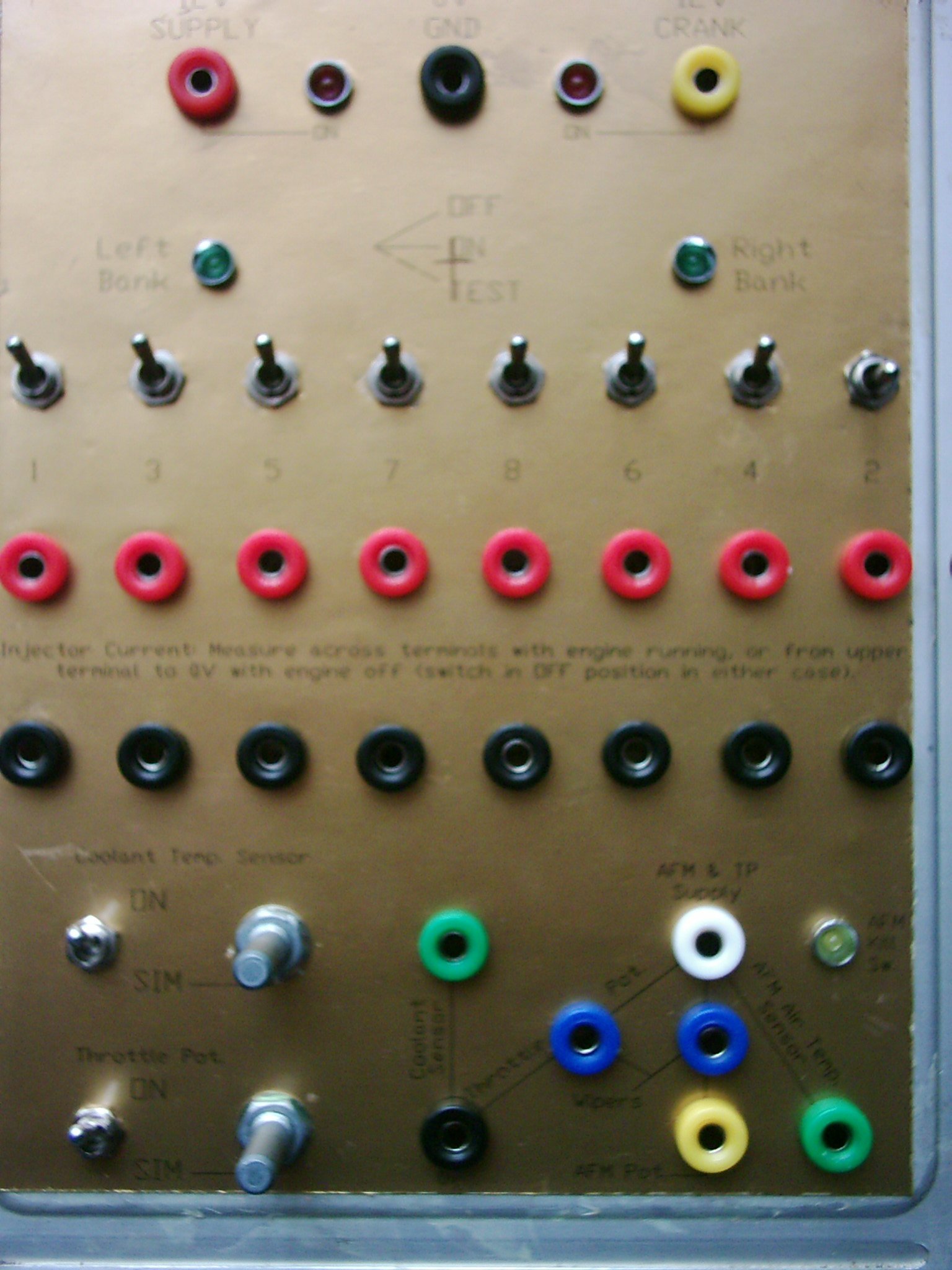
With all the holes drilled, an assortment of switches, potentiometers, connectors and LEDs were installed and wired up to the chopped loom and the chassis connector. The drilling template was enhanced on CAD by the addition of labels for the various parts and was then printed on gold-effect card (it was all I had!) and lacquered.
This sort of thing:
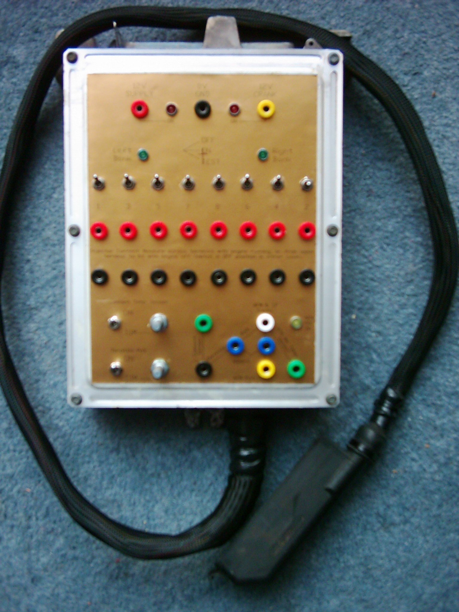
Quick summary of its capabilities:
LED indication of 12v supply and cranking feed, plus LED that shows when the 'kill switch' in the AFM is closed to actuate the fuel pump relay;
Breakout terminals that allow direct measurement of throttle pot., coolant temperature sensor, AFM pot. and air temperature sensor resistances (or the voltages produced by them);
Breakout terminals to allow measurement of the current taken by any injector or, in conjunction with the power resistor module, the resistance of the injector;
Switches to allow any injector to be switched in or out of use, or connected directly to ground to simulate it being fired;
Switches and potentiometers to allow simulation of the throttle pot. and coolant temperature sensor where these are suspect;
LED indication that the ECU is firing each bank of injectors.
Not shown in the picture (as it was an oversight at the layout stage!) is a connector to allow monitoring of the ignition pulses that trigger the ECU.
Within a couple of weeks the tester had shown its value: one day for no apparent reason the car wouldn't start. It had run fine the last time I drove it, but that particular day the engine was just spinning away without catching. I checked to see that the ECU was firmly plugged-in and it was, so I connected the injection tester. As soon as I turned the key I could see no LEDs indicating that the injectors were firing. That points to the ignition trigger input, so I pulled the coil lead off the distributor and rested it on a rocker cover, then cranked. No spark. Which leaves the ignition amplifier or the pickup coil. I blagged a spare amplifier off a mate and measured all the internal resistances compared to the one I had. They were virtually identical, suggesting either both were OK or both duff. I measured the pickup coil resistance and it was 19 MegOhms (should be about 3000 Ohms!). With a new pickup fitted she fired straight up.
So OK, under similar circumstances you'd do the same thing (ie rule out the sparks first)... but the tester certainly did what it was built to do! As a matter of interest, for some time prior to the ignition pickup failing, the car had refused to rev beyond 5300 rpm. I'd tried disconnecting the aftermarket electronic rev limiter but to no avail and had decided it was just down to the mismatched injection components I had fitted. With the replacement pickup fitted, normal (6000+ rpm) service has resumed... :)
December '05... I bought another ECU.... via Ebay, where else? The seller said 'found it in the garage, know nowt about it'.... so I bought it. It bore the label of an auto electrical place in Sheffield, but the PCB looked unmolested. I plugged it into the 390 and turned the key. The car started but ran very rough: a quick glance at the injection system tester showed only one 'bank' LED lit - it wasn't firing the right-hand bank. Apart from that it seemed to respond to throttle input, simulated coolant sensor etc.
So I took the covers off and reached for my multimeter...
The obvious culprits would be the power transistors that actually earth the injectors to fire them. A quick probe with the meter's diode test range did indeed give some slightly odd results. I went a stage further back, to the transistors that drive the output devices. This time there was more certainty that the devices were OK.
So I plugged the ECU into the tester, connected it to the 390, fired up my trusty portable scope and turned the key to get the car spluttering on only the left bank. Starting with the outputs from the main Ferranti IC, I was able to get meaningful and identical traces in both the left and right driver stages. The signals only went wonky around the power devices. With no spares I decided to swap the power transistors between banks; if the fault followed the swap then I had my fault. In the event, a further check with the diode tester on the removed transistors instantly showed the right bank device to be open-circuit.
A quick trip to Maplins (EDIT: remember them?!) turned up some suitable replacements and the ECU was soon back in the car and firing all 8 injectors. Then I noticed that the ECU wasn't responding to the 'foot-down' signal...! Moral: beware when buying unknown ECUs from Ebay...
UPDATE - JAN 2012
Whilst I was in Maplins that time I took the opportunity to stock up on the various switches and connectors needed to build another ECU tester. I thought I could include some additional features to allow further tests on components. It took me a while to get around to it but here it is:
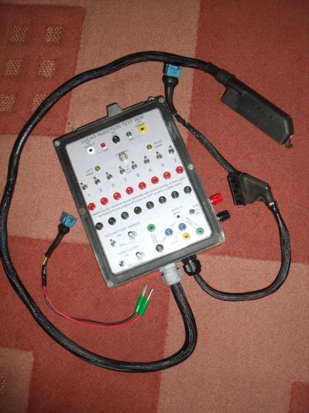
The additional connectors (a) allow the tester to be plugged directly into an airflow meter for bench testing and (b) permit easy testing of the various 2-pin components such as coolant temperature sensor, injectors, thermo-time switch, cold start injector and auxiliary air valve. I can also connect ECU and AFM and power them on the bench, so I'm a step closer to having a 'real-time' but off-car diagnostic capability. In this connection I've also worked out the bones of a pulse generator to simulate the ignition input to the ECU: with that and the airflow meter data taken from a running system I can start to play with the calibration resistors in the ECU :D
I eventually sold the first injection test box but was surprised how little interest there was when I auctioned it. Which seems odd, given how much moaning and hair-pulling goes on around the internet when the Rover V8 injection system causes problems.
I had my 390SE on a rolling-road in 2010 (256bhp/280lb.ft.) and the fuelling graph is, according to the dyno technicians, good enough as to render fine-tuning a 'diminishing returns' exercise. However the nice fuelling curve means that the values measured at the AFM must be pretty close to optimum across the rev range so I can replicate that with another AFM on the bench.
Meanwhile the injection tester proved its worth yet again when I picked up two more ECUs cheaply from Ebay and was able to rough-test them in the warm house rather than the cold workshop: one is more or less OK and the other wasn't giving acceleration enrichment - but I had the PCBs I'd removed from the 'donor' unit I used to build the injection tester so I swapped a particular IC and the fault disappeared.
UPDATE August 2018 - I was contacted by a guy in Hampshire with an SD1 that had been giving his blood pressure a hammering :D As I was working in the area I nipped across and we spent a couple of hours trying to get to the bottom of his running issues. In the process we plugged-in the repaired ECU mentioned above and the car pulled hard... but then started 'trailer-hitching', which is juddering or surging on a light throttle. It is an ex-Range Rover unit though so it could be calibrated differently, and he has an ex-Jag AFM fitted, so that's another variable in the mix... his initial fault was intermittent and had worsened, despite his best efforts to track it down using information available around the internet. For our first test-drive I plugged-in my test box and checked that all injectors were firing and that his ECU seemed to be responding to the throttle pot and coolant temperature sensor. After about 5 or 10 minutes though, the car lost power. Having already expected the fault to be due to solder issues I wasn't too surprised to find two or three questionable joints which were duly reflowed. I resorted to sitting in the passenger seat with the ECU, minus covers, on my knee and as he drove us around for lap 2 I started playing the drums on the circuit boards! You may laugh, but it's surprising how often a good clatter with a screwdriver handle will provoke an intermittent fault into appearing. Except it didn't. Ginger Baker and Lemmy from Motorhead couldn't have paradiddled any harder than I did that evening and I was satisfied that the problem was resolved. So I put the covers back on, the ECU was refitted without the test box and we went for lap 3 of the New Forest. There was just a hint of a stutter a couple of times but the car pulled harder than it had on our first run. I headed back to my hotel feeling suitably smug. Next morning there was a message: the fault was back. I suggested running the car with the ECU covers removed, since the only time it ran properly the covers were off - maybe it's a thermal issue; something in the electronics is getting a bit too warm and leaving the covers off gave it enough air to keep cool. I didn't hear anything for a week or two and then the message came that the owner's patience was exhausted and he was binning the injection in favour of carburettors...!