|
There's a little extra feature on my car that I have yet to see on another TVR Wedge...
Yes, it's cruise control! I don't
know if it was ever offered by TVR as an option (I doubt it!), but I thought it may come in
useful for those long drags down the motorway when my right foot has a habit of
getting carried away with itself...;-)
In the same way that the fuel
injection system was an 'add-on' for the SD1 (and the Range Rover), the Hella
GR65 cruise control system is a fairly simple collection of components that can
be easily liberated from a donor SD1. One or two items are not so obvious and
may be harder to get at, but if you do as I did and buy a system already removed
from the donor car, the hard work is done and you just need to make sure all the
bits are there! In my case they weren't, but more of that later...
So, what's involved? The cruise
control works quite simply: you get to a speed that you'd like to maintain,
press a switch and the car maintains that speed. You can over-rule the cruise
by accelerating (say, to overtake something) and certain safety features are
included to stop you doing something that could break the car, or yourself!
1. First off, you need a cruise ECU.
Packed with digital electronics (in a 1980's sort of way!) the ECU performs the
calculations of road and engine speed and sends signals to the vacuum system to
adjust the throttle.
2. Vacuum system? Yep, there's a
miniature vacuum pump and solenoid valve that creates and controls the vacuum
necessary to operate...
3. The vacuum servo (or 'bellows');
which is linked to the throttle assembly by... well, a bit of stiff wire! This
was improved later to a slotted link and can be found more easily on Range
Rovers as more of them had cruise control.
4. Of course the ECU needs to know
how fast the car is travelling; this is measured by a sensor mounted on the
gearbox that detects the rotation of the propshaft - now this is my main
sticking point, since the sensor drove the electronic speedo of the SD1 in place
of the cable-driven version. The older (Dana) cruise system uses a small magnet
mounted to the output flange of the gearbox; as it passes the sensor a pulse is
generated that is fed to the ECU. The faster the prop turns, the faster the car
is going and the more pulses are generated (when I started looking into installing cruise I thought I may have to adapt this idea
to drive the Hella system, as the TVR of course uses a cable-driven speedo). I
didn't get the Hella's pulse generator with the rest of the system, but managed
to source another via Ebay.
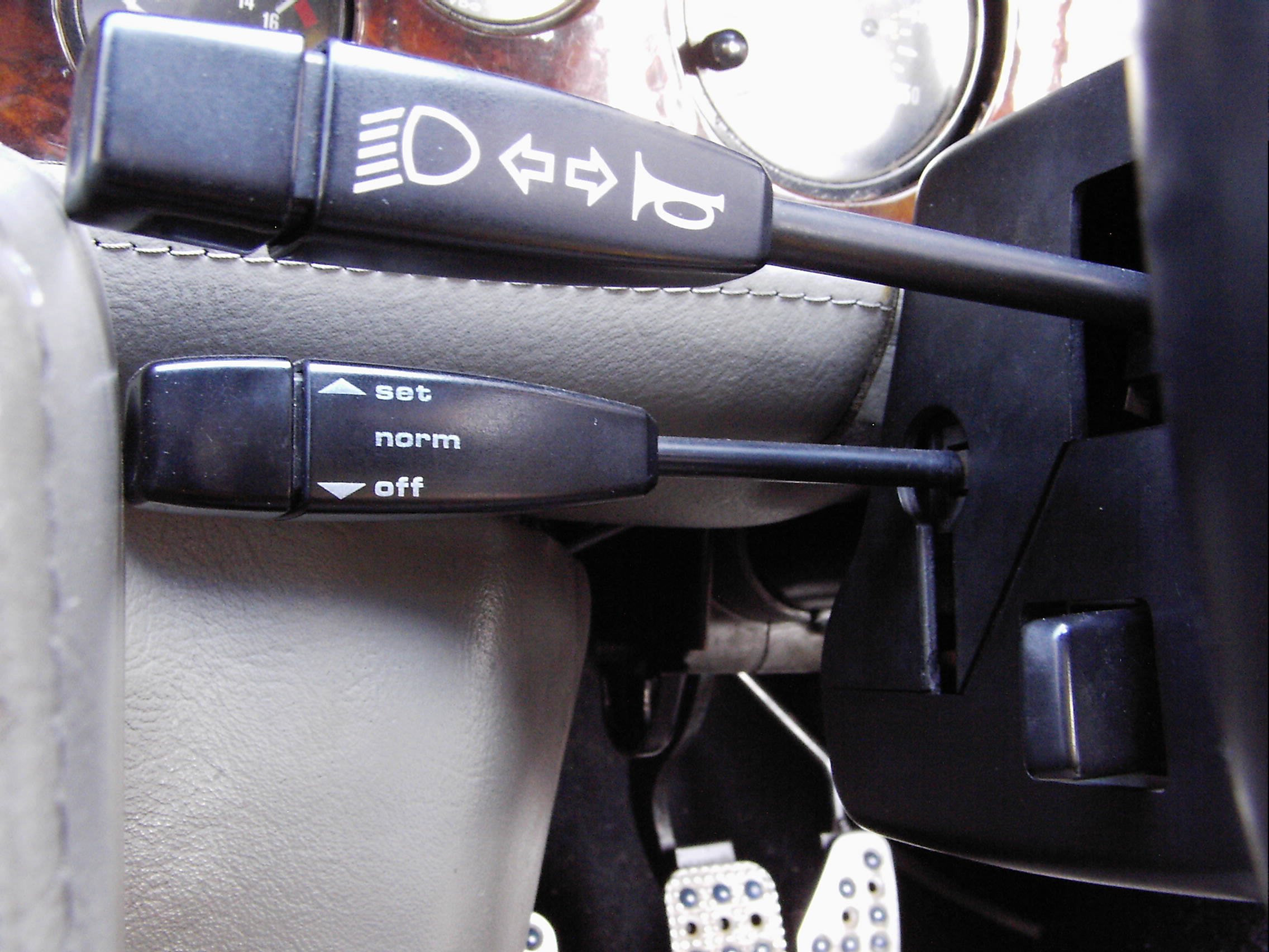
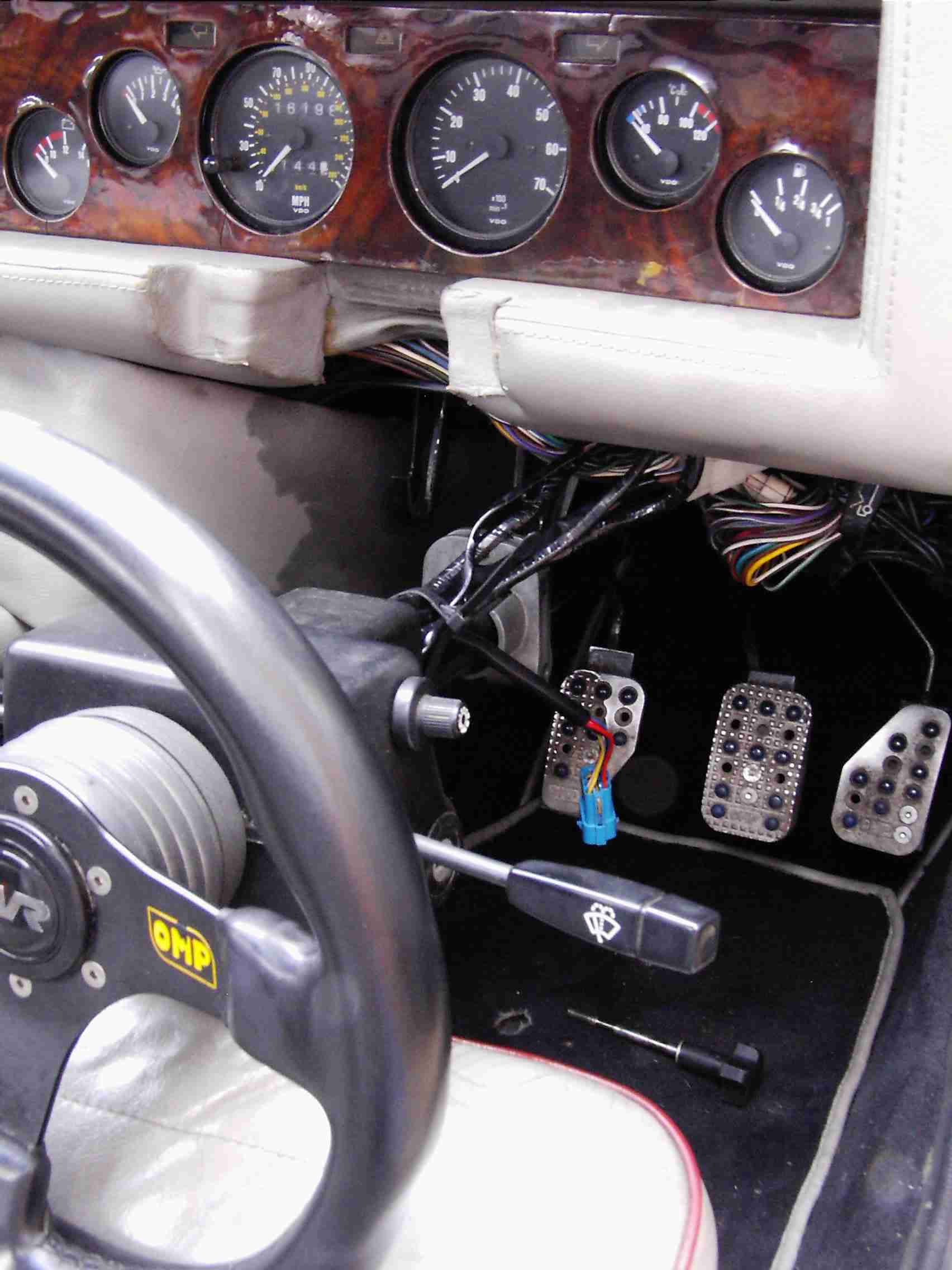
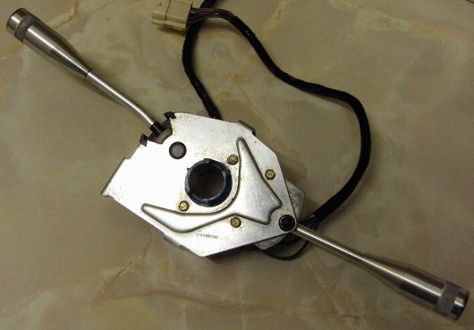
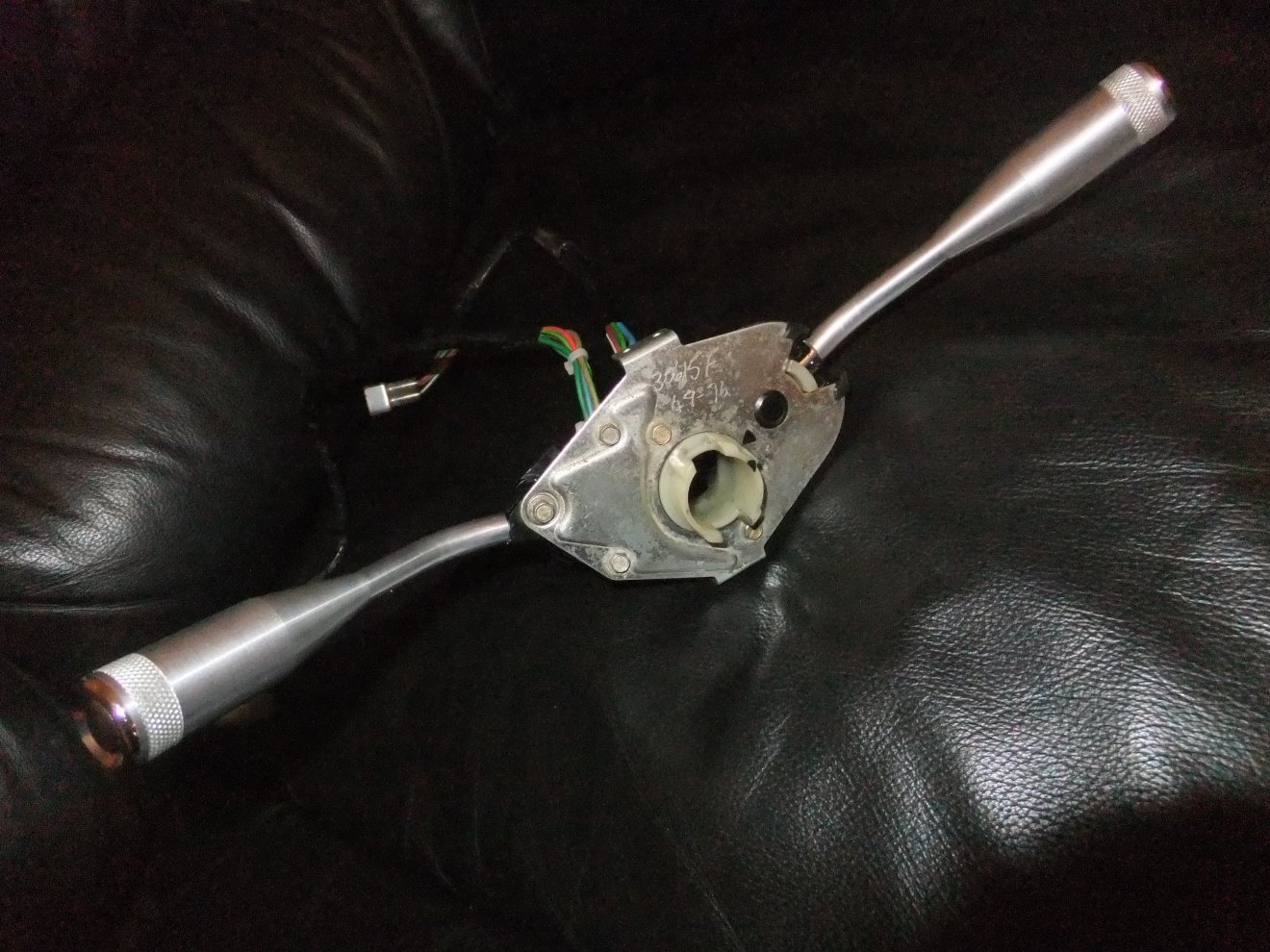
5. Steering column control switch.
As seen in the picture above. Tells the ECU when the cruise is required, when
it's not, and when it is again. More or less. Quite a neat solution, from a
retro-fitting point of view. A lot of cruise-equipped cars had/ have the cruise
functions selected by switches in the steering wheel, so you need to change the
steering wheel. Luckily BL were cheapskates and did it this way instead :D The
only minor change was to the upper column shroud, which has a new cutout to suit
the cruise switch. It wouldn't be absolutely essential to have this shroud from
the donor, as the existing one could be modifed with care. The cruise switch has
its own mounting bracket which screws to two holes thoughtfully provided in the
rear of the indicators/dip/main/horn switch, so again, as long as you get the
cruise switch itself, the existing switchgear can be retained - as long as your
TVR still has SD1 switchgear, that is. I have actually seen a couple of TVR
Wedges with the modified upper shroud, but no cruise. I guess TVR fitted
whatever they could lay their hands on that week... ;)
6. Overspeed relay. Detects ignition
pulses and cuts the cruise if the engine revs exceed a certain point: this stops
you engaging cruise in a low gear and over-revving the engine trying to get
there! I think the limit for the V8 is 5400 pm, which in the TVR would be
something on the wrong side of 125 mph in top...
7. Pedal switches. Fitted to the
brake and clutch, these are cut-out switches that tell the ECU to release the
vacuum if either pedal is depressed (braking, or changing gear...) as otherwise
the engine would rev to the skies, or try to fight the brakes. As well as an
electrical contact, the switches also incorporate a valve that opens the vacuum
line to atmosphere, rapidly releasing the vacuum servo so the throttle closes
quickly, as opposed to switching the cruise off by the column switch which
slowly releases the vacuum to slow the car smoothly. Some thought will have to
be given to how best to mount the switches on a Wedge as the pedal box wasn't
designed with cruise control in mind.
8. Wiring loom and main fuse - as it
says, a dedicated section of wiring with all the necessary connectors and fuse
to supply the components of the cruise system.
A selection of brackets were also
used to mount the cruise components on the original car; some I used but most I think were scrapped.
I assembled
the cruise components and established that they worked, which took a bit of
thinking about - I bypassed the overspeed relay; one wire has to be earthed to simulate connection via the brake
lamps - some sort of safety feature; the speed pulse generator needs a load resistor as
the electronic speedometer isn't present... but apart from that it was simple enough.
I used a cordless drill to spin the
pulse generator; pressing the 'SET' switch caused the vacuum pump to fire up and
suck the bellows unit. Speeding up or slowing down the drill made the bellows
extend or retract just as it should.
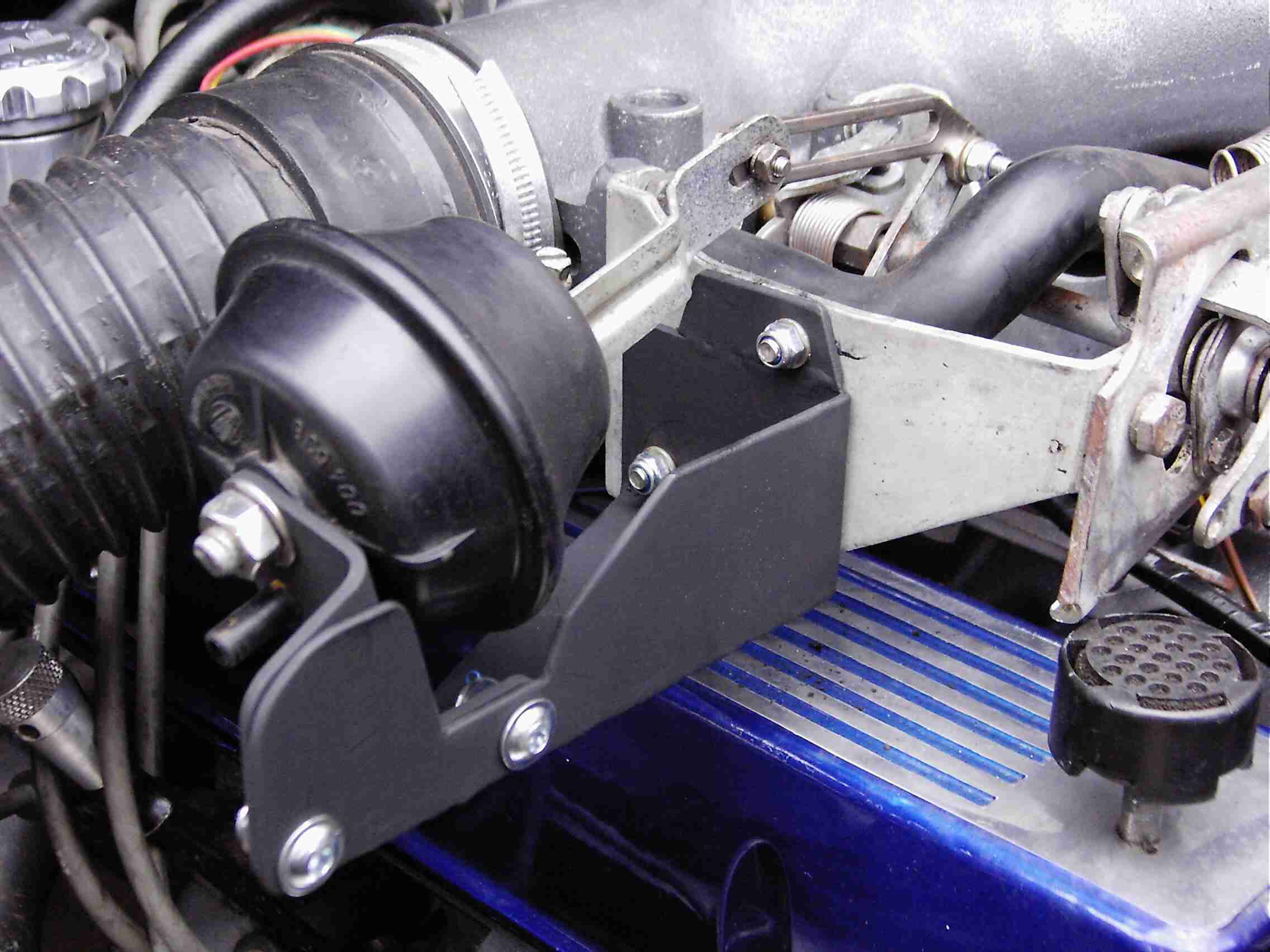
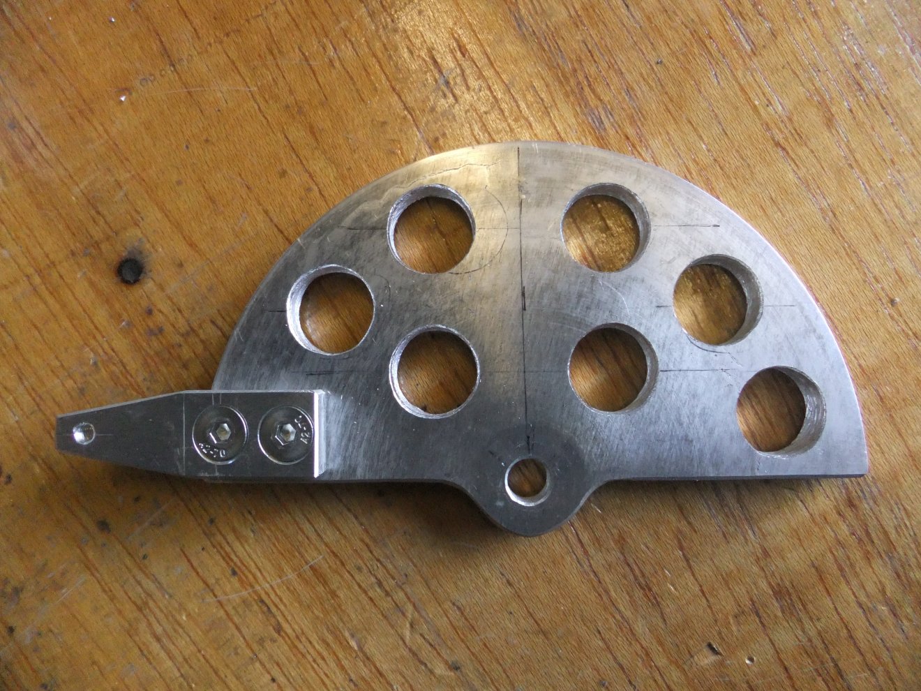
So, how to fit the bits to the car?
The column switch was far and away the easy bit as it simply screws to the rear of the existing indicator switch. The pedal box had
to come out, which meant dropping the steering column, the clutch
master cylinder and half the wiring loom... but first I considered the bellows
unit. There are two obvious points where the bellows could pull on the throttle
linkage, but only one of them seems to allow a proper arc of travel. So with a
bit of measuring and some guesswork, a piece of steel plate was cut and drilled
to support the bellows off the side of the existing steel bracket, using two
bolt holes thoughtfully provided:
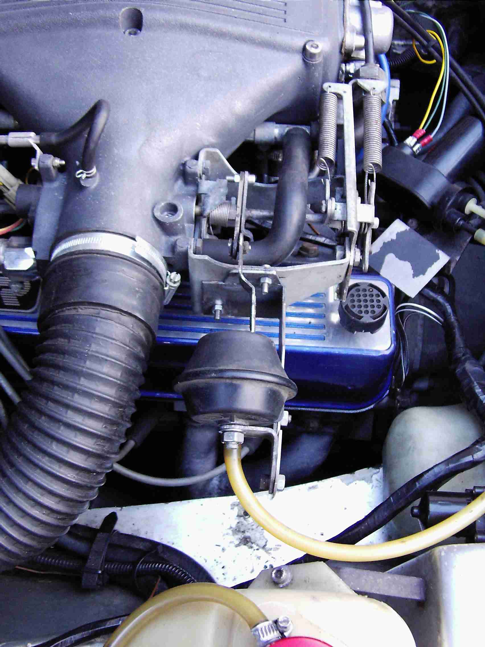
The TVR uses THREE throttle return
springs. I wondered whether the vacuum pump and/or bellows would be able to pull
the throttle against such resistance. Firstly I tried sucking on the bellows and
that seemed to work OK, so I temporarily connected up the pump and applied
power. It worked!
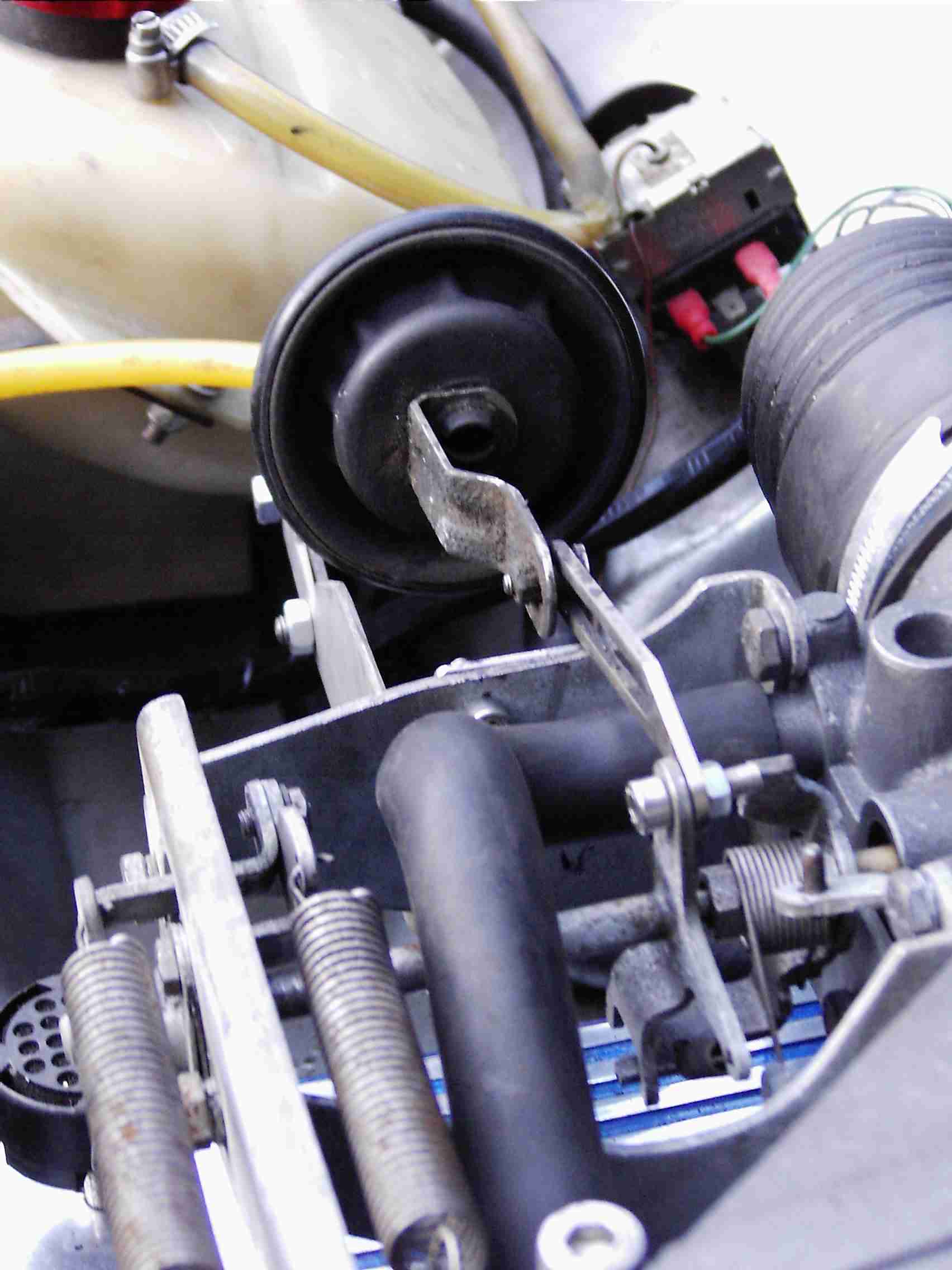
Finally, I checked to make sure that
the throttle linkage could work through its full range without the cruise
linkage fouling it. All OK there. There was a slight flexing of the new bracket but not enough to prevent
the bellows working; later I added a welded gusset to stiffen the bracket.
Next I pondered whereabouts to site
the vacuum pump. I settled on the inboard side of the GRP moulding that
surrounds and supports the pedal box. This position keeps the pump out of the way of just
about anything that I'd be likely to need access to, whilst leaving it handy for
electrics and vacuum pipework. I tried the original mounting bracket every which
way but couldn't make it fit so I gave up and fabricated one - a simple L-shaped
affair - with captive threads for the pump mounting screws.
I grovelled around in the footwell but it was obvious there was no other way: the pedal box would have to come out.
There was no way I was even going to attempt to weld brackets to it, down in the
depths of the footwell. Luckily I had a couple of days off work. It looked like
I might need them...
As it turned out, it wasn't all that
difficult a job. Before you can extract the pedal box, the steering column needs
to come out. This means disconnecting the upper universal joint in the wheelarch.
Disconnect all the multiplugs from the column switchgear (snipping cable ties as
you go!), remove the two nyloc nuts holding the clamp to the support strut and
the column should drop onto the driver's seat. At first glance it looks as
though you could unscrew the column clamp knob from the rake/ tilt assembly and
drop the column that way, but there's a cunningly-placed roll pin to stop you
removing the clamp bolt. Once I had the column out I knocked this out and
replaced it with a split pin in case I ever need to drop the column again.
Here's the roll pin:
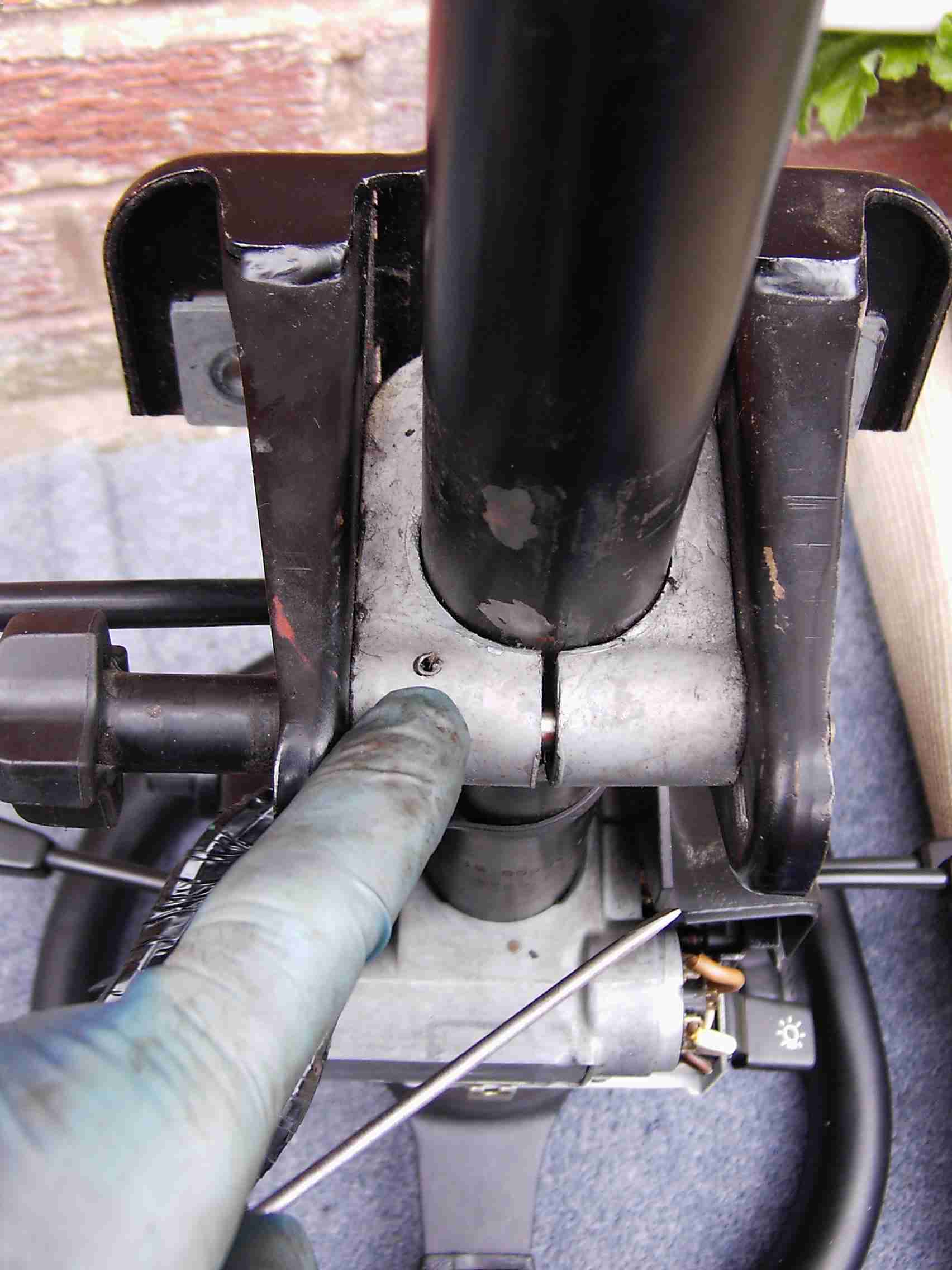
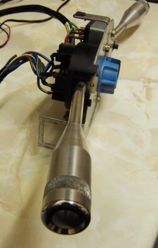
The column with it's mounting and
rake/tilt clamp:
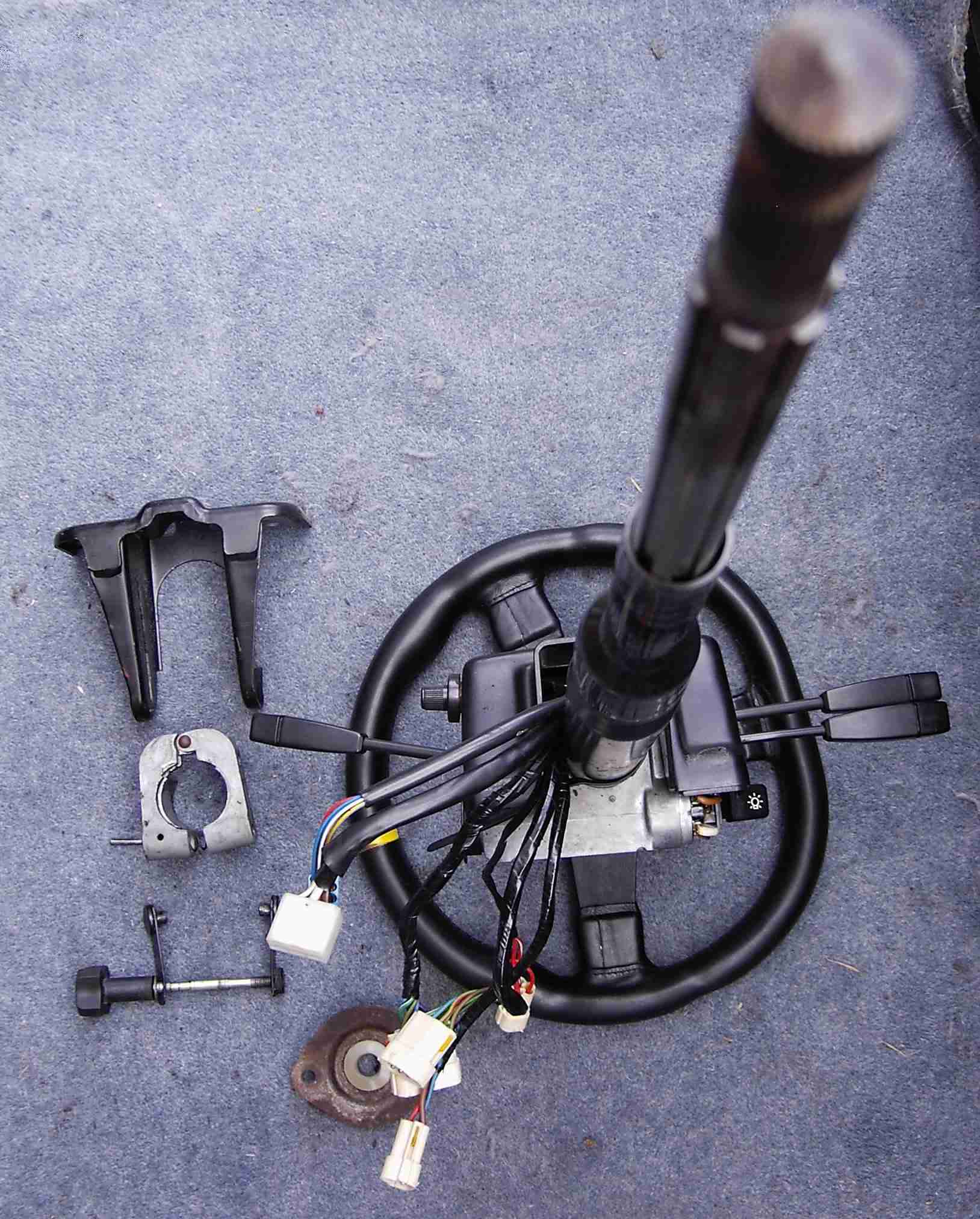
Eagle-eyed readers will spot that
the lights switch appears to be upside-down: you can pull the lever off and
invert it. The rusty elliptical thing at bottom left is the bush that
supports the column where it passes through the footwell; there's a bit of play
so it needs replacing. More on that
here...
Four nuts hold the pedal box to the
brake servo; two more secure the clutch master cyl.; two bolts hold the box to
the scuttle (the ones just above & behind the brake servo when seen from the engine
bay). Two of the servo nuts retain the throttle pedal on a separate bracket; the
throttle cable needs to come out as does the bonnet release cable and the speedo
cable. With the clutch and brake pushrods unclipped from the pedals and the
brake light switch wires detached, it was just a matter of wriggling the pedal
assembly out from under the dash (apologies for the chav-tastic pedals, previous owner's doing!):
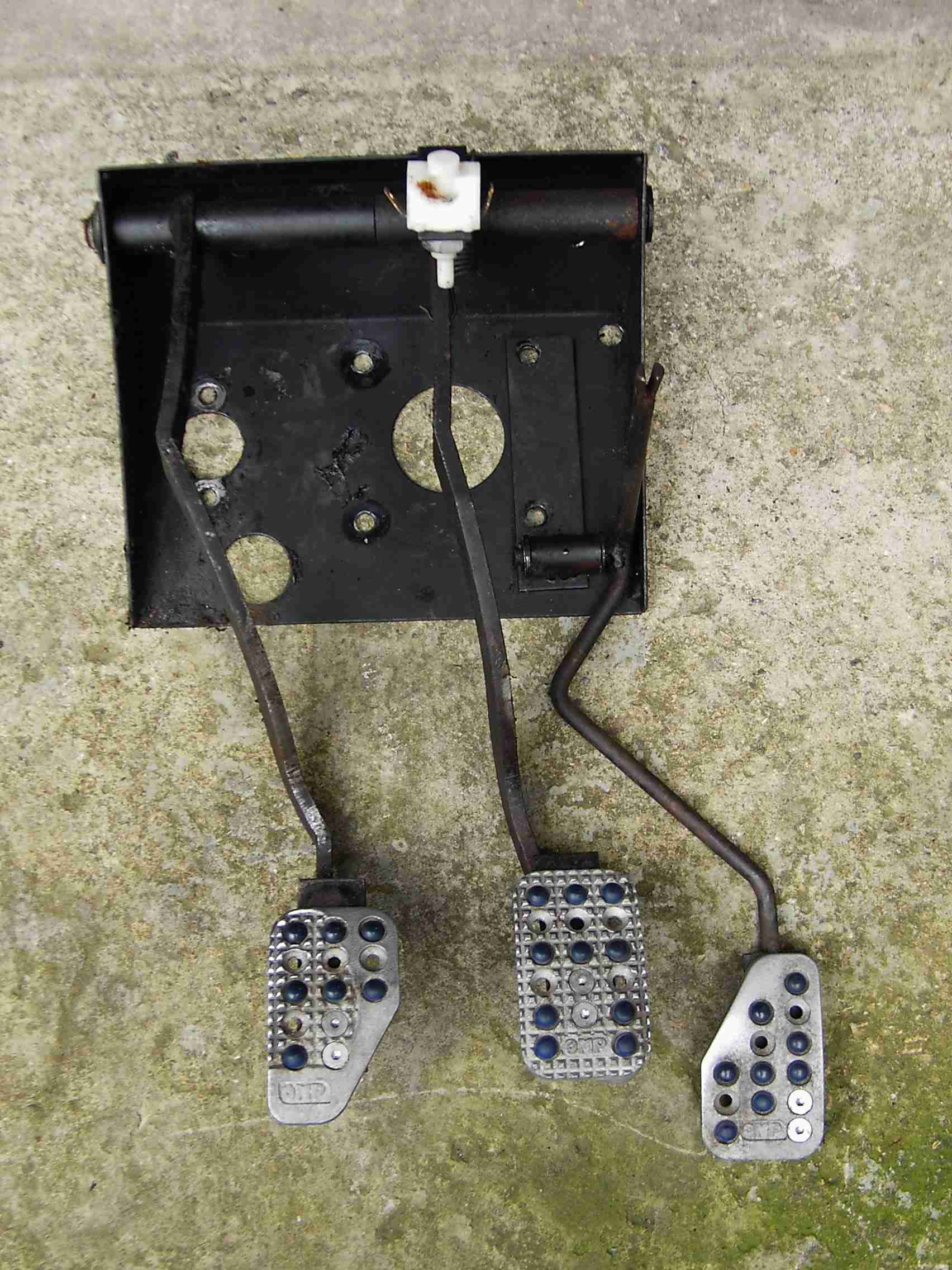
Although the steelwork had been
plastic-coated there were a few patches where clutch fluid leaks had removed the
coating. I took the opportunity to sandblast and repaint these areas and also
the pedals themselves. I played around with the cruise release switches and
fabricated some simple brackets (in the style of the existing brake lamp switch
one!) to locate them. These were duly welded and painted, then the unit
reassembled with fresh grease.
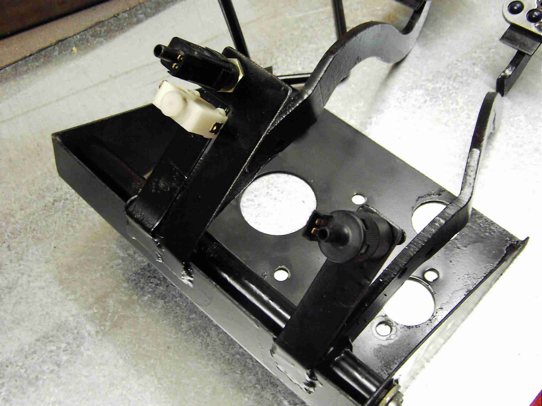
The white switch is the brake lamp
switch and the other two are different versions of the Hella release switch. The
simple strap brackets allow the switches to be adjusted relative to the
pedals.
Whilst the paint was drying I took
the opportunity to mount the vacuum pump
using self-tappers, with a smear of silicon sealant to keep the water out:-
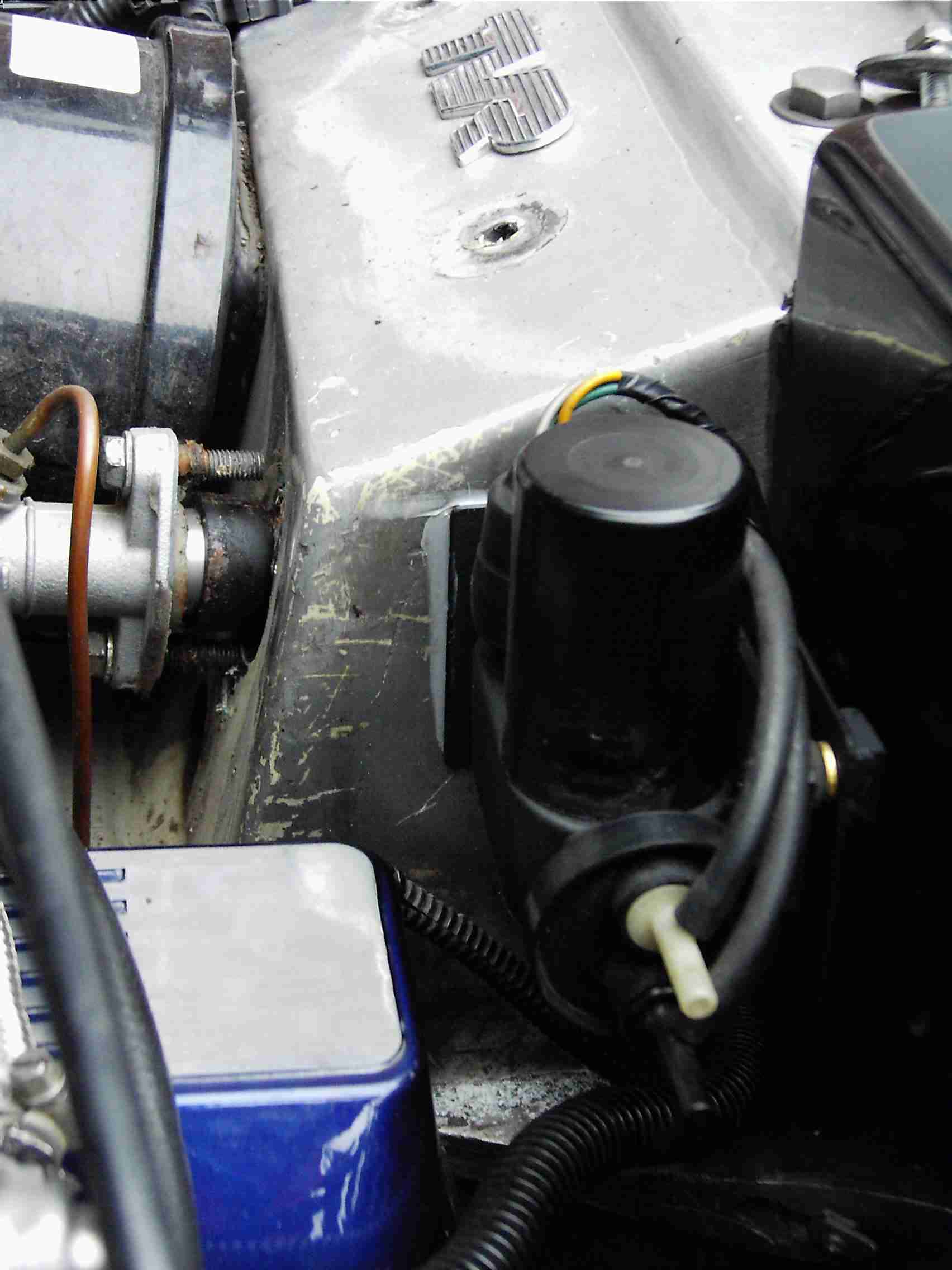
The vacuum servo almost looks
original! I got my paint cans mixed up: the finish was supposed to be satin
black, not matt! You can see the slotted link that allows free movement of the
throttle linkage when not in cruise mode:-
The remaining stumbling-block was how to provide the electronic pulses
that the cruise ECU needs to know the vehicle's speed. The earlier SD1s (and the
TVR) used a cable-driven speedometer, whereas the later SD1s gained an
electronic instrument pack that included fuel economy information. This used
a sealed pulse generator that was fitted to the gearbox in place of the cable
drive. I could use one of those but then I'd lose my speedo. I'd seen a couple
of later TVR wedges that used an electronic pulse generator fitted in-line with
the speedo cable, but they were used to feed speed information to the fuel
injection system ECU to aid the idle stabilisation. Then I discovered that some
Range Rovers used the same pulse generator either for cruise control or just to
drive an electronic speedometer, so of course I HAD to get hold of one to try.
One rummage on Ebay later and the pulse generator was installed to the system
and spun-up with a cordless drill. It worked! The SD1 electronic generator
normally used with the Hella cruise system is a 'proper' sealed bit of
electronics where the (Jaeger) device from the Range Rover is simply an 8-pole
magnet spinning in close proximity to a reed switch. Whether this would cause
issues, e.g. with contact bounce would only become evident over time. I locate a suitable
(split) speedo cable with which to complete the installation. Having plumbed the vacuum lines in (I used 5mm airline tube and push-fit connectors, should be OK for vacuum as the pump will compensate for any leaks!), the next stage was to find space to locate the cruise ECU and overspeed relay and wire in the pedal switches.
Needless to say, the combination of LT77 gearbox and VDO instruments on the TVR results in a speedo cable that appears to be incompatible with anything from any car manufacturer in the known universe, let alone anything that would have a split cable! I'd heard about Speedy Cables so I fired off an email to see if they could make me something; the reply was positive enough that I chucked the old cable plus the speed transducer into a Jiffy bag and sent it winging Wales-ward. A fortnight later another Jiffy bag appeared containing exactly the right bits to do the job! From my recollections of other Wedges I'd seen with the same speedo transducer, it was fitted into the cable in a position that left it in the engine bay. I asked Speedy Cables to position it just a few inches from the speedometer end so that it'd remain in the cabin.
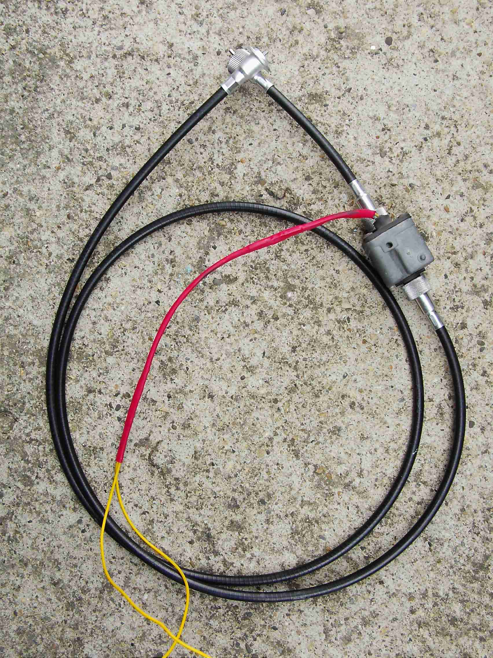
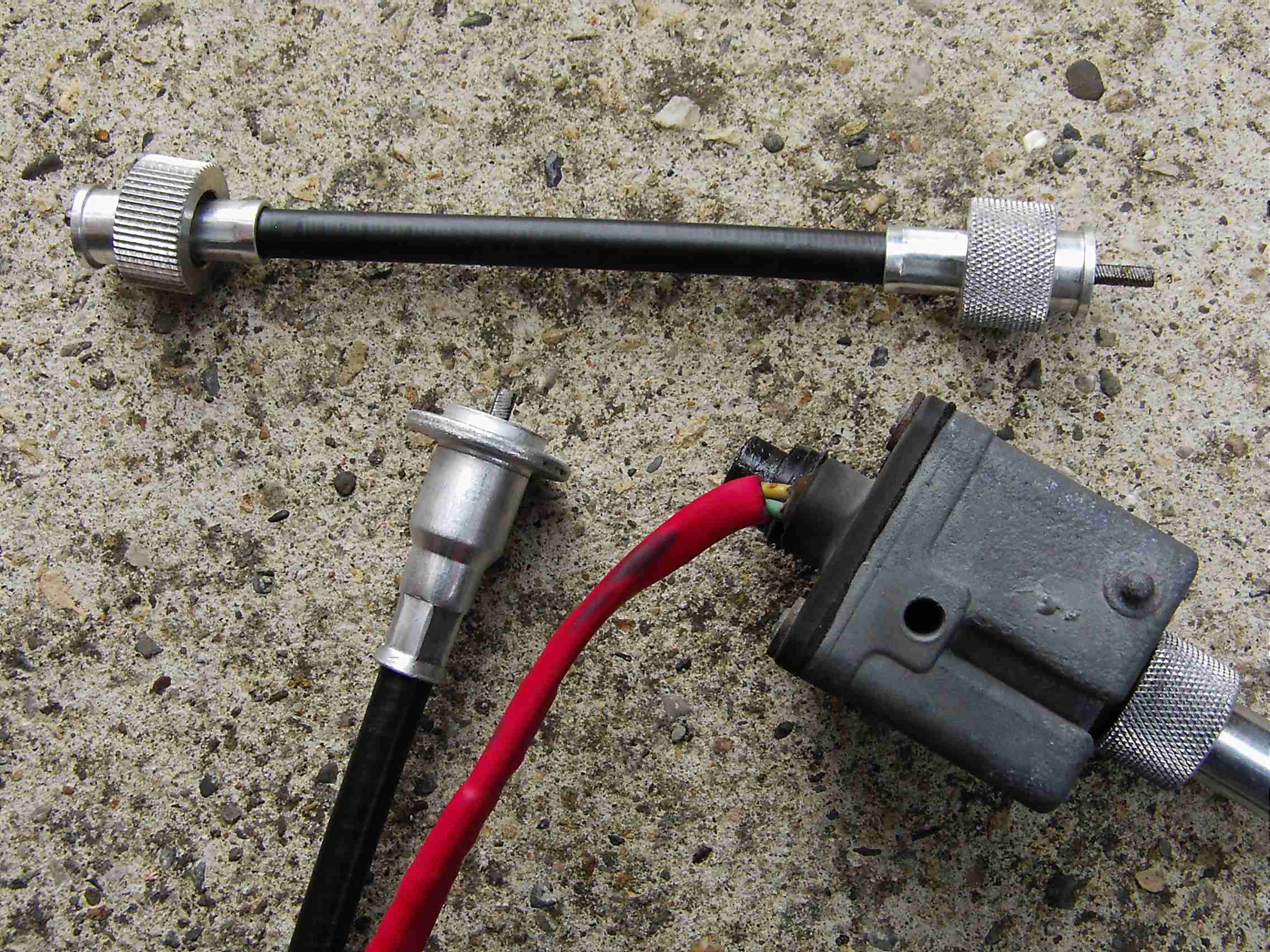
The only slight hiccup was with the knurled nut that secures the upper cable to the rear of the speedo: the nut was too deep and wouldn't pull the cable firmly against the speedo boss. A few seconds dressing with the bench grinder easily reduced the depth and the cable nipped up securely. Pic shows the cable before doctoring, it's the nut at left end of the short cable that needed work:
To make access easier I whipped out the split pin mentioned above and dropped the steering column onto the driver's seat. The lower bearing protested a bit as it had to move in its housing to accommodate the movement but it coped OK...
The ECU and overspeed relay were simply mounted (read: shoved) behind the centre radio console. This left the wiring loom nicely positioned so that it ended under the instruments. I had to run two wires across the cabin to the passenger footwell; one ties in to the ignition pickup feed that triggers the fuel injection and the other I spliced in to the boot lock fused feed (can't see me trying to 'cruise' and open the boot at the same time!). The brake and clutch pedal switches were wired in series; the column switch simply plugged in. Suddenly... it was finished! Time for a drive then. I took along the wiring diagram, multimeter and spare fuses but I needn't have worried. I hit the local dual carriageway and sat at about 40mph. I pulled the stalk towards me to energise the cruise system. Then I tapped it upwards to 'Set' and slowly lifted my foot off. With just a slight surge the cruise control took over and I was able to test the controls. Below about 35mph the throttle response gets a bit ragged, it's rather on/off, on/off... but that's hardly where you'd use cruise. Up at 70/80 mph it's spot-on. Mind you, exiting a roundabout in second gear and hitting 'Resume' when you were just doing 80 gets interesting... 8^0
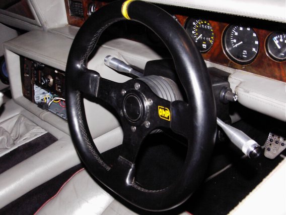
Meanwhile, I'd pondered a few times over the spindly column switches that TVR robbed from the SD1. With the 390's smaller steering wheel, the stalks stuck out some way either side and the indicator lever was forever getting stuck against the radio console! What was needed, I thought, was some shorter stalks. Preferably not spindly. Preferably more 'in keeping' with the other cabin accessories, like the alloy gearshift knob and alloy handbrake. I know! I'll make some new stalks... out of alloy :^D
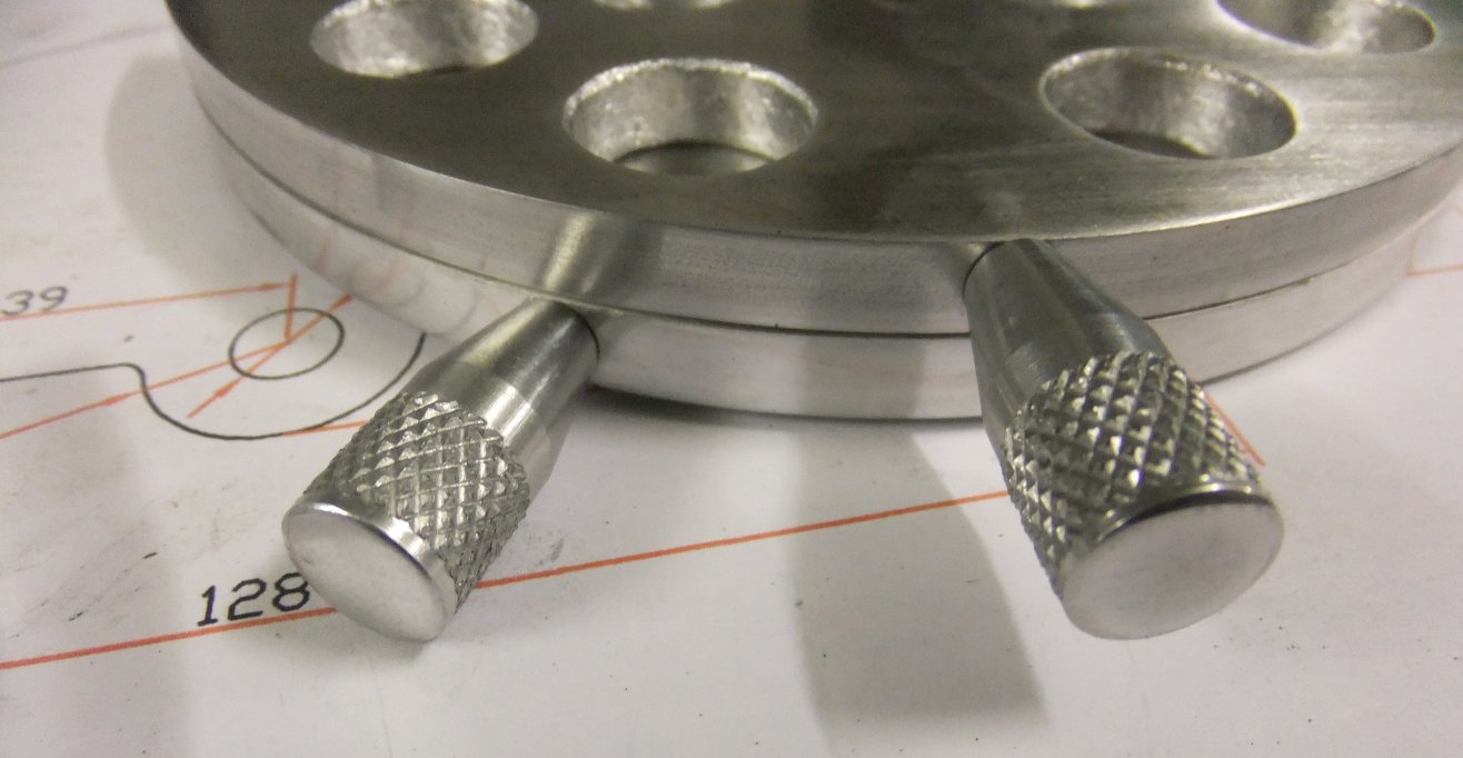
Now I'm by no means a skilled machinist so attempting to replicate the existing switches with their push-button ends for horn and screenwash was a non-starter. What I needed was some ready-made pushbuttons, around which I could design the 'stalk'. I duly found some stainless steel pushbuttons that have threaded bodies. Some aluminium bar was then bashed about on the lathe - drilled, turned, bored, knurled, threaded and generally reduced to swarf on the floor - resulting in these:
I think they're still a bit long (though they're an inch shorter than the SD1 originals) so now I know what I'm doing (ahem) I'll have another go. Of course I'll need to make another one for the cruise control as well! Here's the new switchgear on the car:
...and with the alloy gearshift and handbrake:
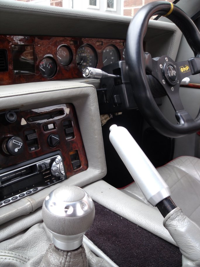
I thought those heater controls might look better in aluminium.... :^D
... and indeed they do (or at least they will when they're finished!).
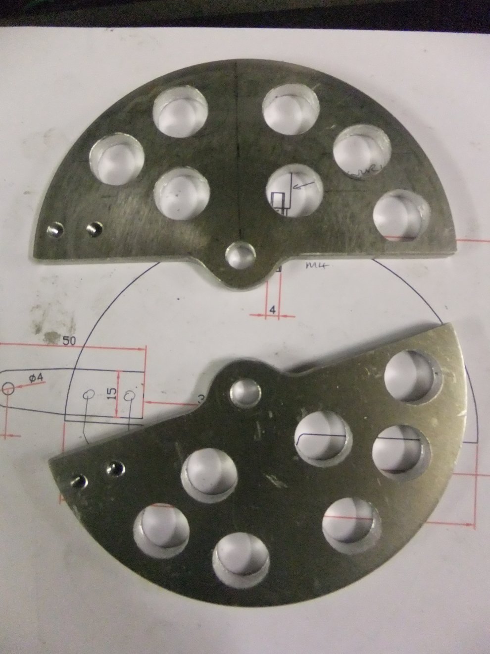
The large holes are in response to someone who pointed out that I was adding excess weight to the car...!
Meanwhile, a fellow Wedge owner had spotted my alloy switchgear at a TVR meeting and persuaded me to make him some for his early Tasmin. The Tasmin used Trumph TR7 column switches and the levers were more bent than those on the SD1, but with some care I made these for him:
Back to top
Back to Wedges
Back to Home
|