Headlamp horrors!
Pop-up headlamps. Don't you just love them ;)
They're great when they work, but when they don't, I reckon they must be the greatest source of consternation amongst Wedge owners... but it's not rocket science!
The headlamps (bog-standard 7" 60/55W halogen reflector/ lens units with replaceable bulbs) are mounted in fibreglass pods. The pods hinge on two bolts that screw into captive nuts glassed-in to the shell, each side of the pod recess. Usually the bolt heads are cross-drilled to allow lock-wiring the bolts to prevent them unscrewing themselves.
Each pod has its own lift motor, mounted on a steel bracket that, depending on model, year, which way the wind was blowing, is bolted to either the floor of the pod recess or the front wall of the engine bay. If the latter, you can see the screw heads when you open the bonnet. The motor itself is as used on the Triumph TR7 , however the bracket is a TVR fabrication. To all intents the motor is a Lucas wiper motor that goes back to at least the E-type Jaguar, modified (at casting level) by Lucas for the purpose of lifting headlamps (it has two 'park' positions instead of just one) and can be serviced in much the same way. I've created a stripdown sequence for the pod motors in case you need or want to tinker!
The motor is tied to the pod by an operating arm and an adjustable link: again depending on the car, the link can be constructed in a variety of ways but the essence is to allow a degree of adjustment to get the pod flush with the bodyshell when retracted. Be aware that if you alter the link to change the height of the pod when raised, it won't close flush. Also note that the crank arm fitted to the motor spindle was supplied in different lengths for different applications; it's stamped with a number like "1.782" which is the distance in inches between the spindle axis and the operating pin centre.
Most people are fine with the mechanical aspects of the pod system, it's the electrical operation that stumps them. Here goes...
Firstly, the motors only rotate one way, they do not 'reverse' to make the pods retract once extended. So there is no 'polarity reversal', unlike say, a window lift motor.
Each motor has a simple switch and two diodes in the wheelbox. The switch has a common contact and two 'outputs', to each of which are soldered the diodes. The switch contact is a simple copper strip. The common supply terminal is riveted to the strip, this provides one of the potential trouble-spots as the rivet can corrode and lose its connection to the strip. Next in line for grot are the contact pads at each end of the strip. These should be cleaned of corrosion, arcing deposits etc. The two diodes are common silicon rectifiers of the '1N4000' family - 1N4000 to 1N4007, but anything of similar ratings will work.
Before we move onto the flow of electrons, can I just point out for owners of other cars using these same lift motors: there is NO definitive circuit diagram for how to power them. Triumph, TVR, Lotus and Reliant (on the SS1) each came up with their own interpretation of the supply requirements. So don't use what's here (for the TVR) as more than a guide to what's going on elsewhere.
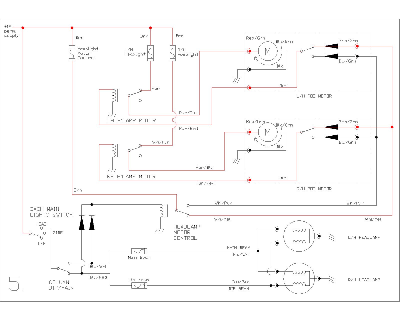
Three relays are used for the basic lift/ lower switching. Further relays are used on cars with extra driving lamps, but for our purposes we will consider a straightforward installation as used on the earlier Tasmins. Reference should be made to the circuit diagrams which illustrate the flow of current at the various points of the lift/ lower cycle. Note that some colour coding of the wiring may differ from your car. I've coloured red whichever wires are 'live' (ie at 12v) for each part of the cycle:
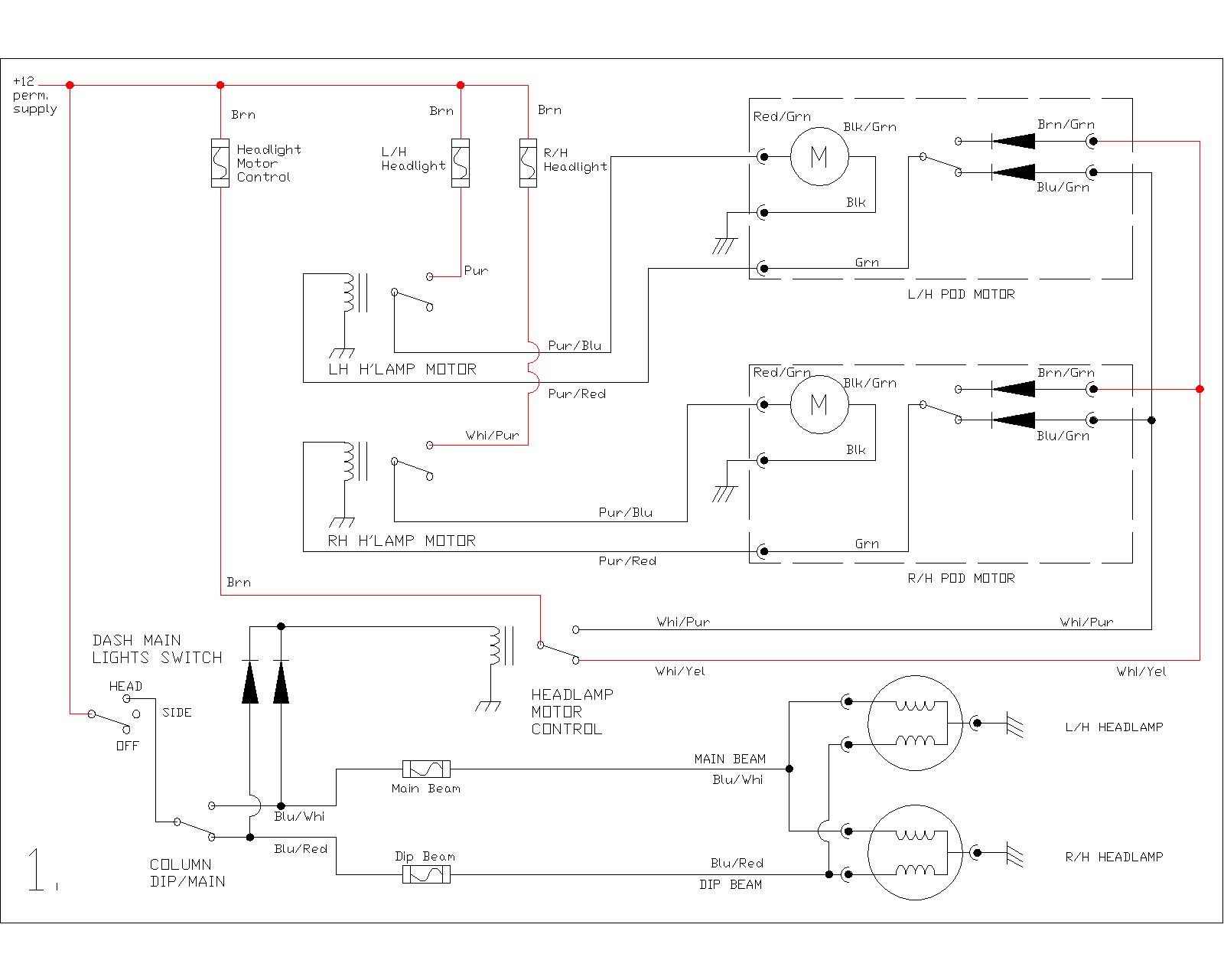
1. Lights are off. 12v appears on the Whi/Yel to each pod motor but can go no further as the motor's internal switch is open.
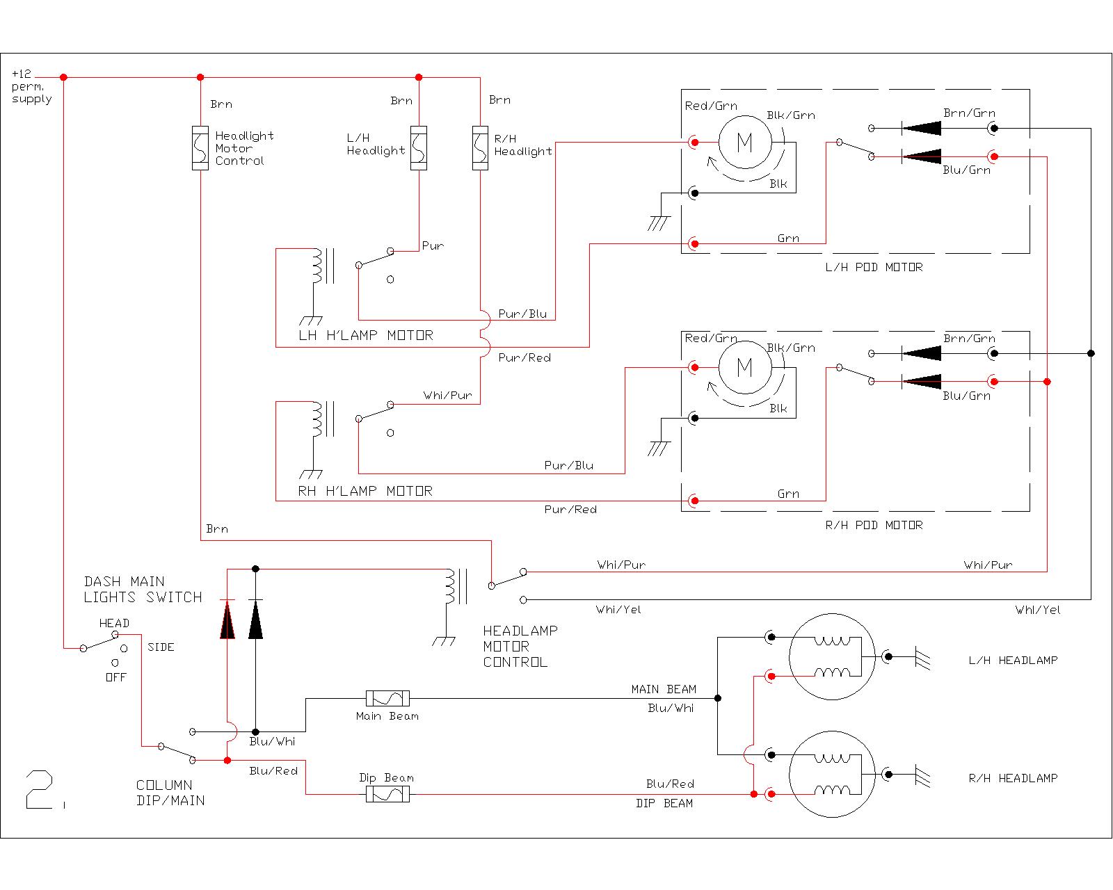
2. Lights are on (Low Beam). A 12v feed appears at one of the two diodes feeding the coil of the Headlamp Motor Control relay. This causes the relay to change over and it applies 12v to each pod motor via the Whi/Purple wires. Passing through one of the motor internal diodes and the closed switch contact, it is fed back to the coil of the Motor relay. The Motor relay changes over and applies 12v to the motor itself, which then starts to lift the pod. Note that the motor's internal switch stays closed during the lift cycle.
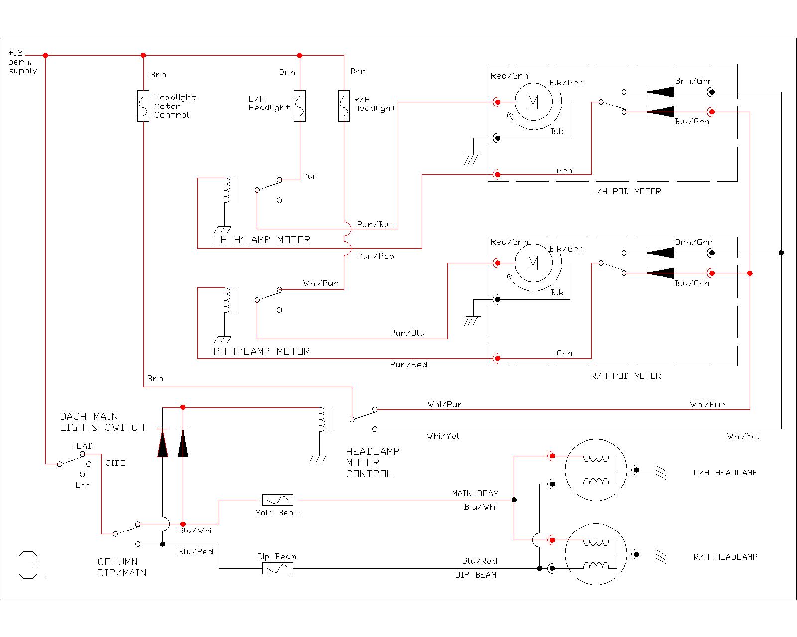
3. Is the same as 2. but shows main beam selected instead. This is why the two diodes feeding the Headlamp Motor Control relay are so important. If either fails the pods won't lift although the lights will be on. Someone asked how come the pods don't drop as you switch from dip to main beam and vice versa, since there would momentarily be no feed via either diode to the Headlamp Motor Control relay. The answer lies, I think, in 'flux remanence' or 'back-EMF', in other words for the split-second it takes the switch contacts to change over, the magnetic field created by the relay coil doesn't have time to completely collapse so the relay stays on. It's definitely not a function of the Lucas column switch, i.e. there is no 'make before break' action - it's a simple snap-action switch where the moving contact shifts rapidly from one fixed contact to the other - and can be seen to do so, as it's not a sealed switch.
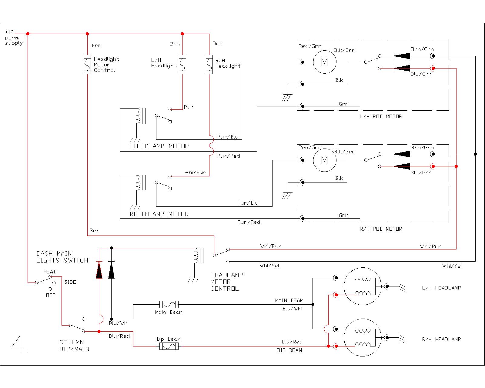
4. The motor has lifted the pod and at this point the internal switch changes over. This breaks the feed to the Motor relay which drops out, disconnecting the pod motor.
Knowing the cycle of operation, it is possible to fault-find on the headlamps fairly rapidly.
The presence or absence of either main or dipped beam can be a clue as to whether the pod motors themselves are faulty: a defective ‘Lights’ switch or column dip/main/flash switch can make it appear that the pods are faulty. Simply peering into the headlamp recesses to see if the headlamp bulbs are lit will help here!
Now, whilst the foregoing is probably enough to help you fettle an early Wedge, things got complicated when the later cars acquired driving (or fog) lamps, some legislation changed, etc. etc... so you may need:
In case you missed it further up the page, you can see a stripdown of the pod motors here....
The pod motors have a knob fitted to the lower end of the armature (rotating shaft), accessible through a hole underneath the car. Very occasionally the holes aren't there! The knob allows you to manually wind the pods up if the electric lift system fails.
To gain access to the pod motor it is first necessary to raise the pod, either manually or by turning the lights on. If you put the lights on, it is a good idea to then pull the fuses so you don't flatten the battery. It's also a good idea to pull the pod motor fuse, especially if you have an intermittent fault that may suddenly wind the pod down while your hand is in it! You could of course disconnect the battery while the pods are raised.
With the pod up, you may find a trim ring around each headlamp; the chromed tin ones can be in a parlous condition but replacements are still available, they're just standard 7" units. To get away from the chrome era TVR fitted some later cars with black plastic trim rings that look to have been either moulded in-house or butchered from some other item - the finish of the cut edges on my car's trims is rougher than a gay hedgehog's arse-cheeks. Anyway, with the trim ring removed you should be able to identify the self-tappers holding the headlamp bowl into the pod and with however many of those removed the bowl will fall out (literally, make sure you hang onto it). Trace the wiring from the rear of the light and you should find a 3-pin connector you can unplug to allow the lamp unit to be removed. Peering into the gloom will reveal the pod motor and a bunch of wiring (the main loom passes down inside the left wing and exits into the nose behind the left-hand headlamp)
Either disconnect the link from the pod or from the lift motor (I usually just remove the nut from the motor shaft), remove the lockwires and unscrew the pod pivot bolts to allow removal of the pod. There's usually a 'stop' bracket screwed to the bottom front edge of the pod that will stop you lifting the pod straight out; you have to drop it down and backwards to create some clearance. The motor can then be unscrewed from its mounting and unplugged from the loom before removal to a bench - or the bin, if it's really bad! - although they can usually be brought back to life as long as the armature's not burned-out and the nylon gear hasn't stripped.
As I don't have a dedicated page for all things wedgy and electrical, here might be as good a place as any to post this diagram, showing the relay 'map' from my 390SE. This is a modified version of the actual diagram that was stuck to the ECU on the car, I had to scan and 'Paint Shop' it to get the correct layout!:
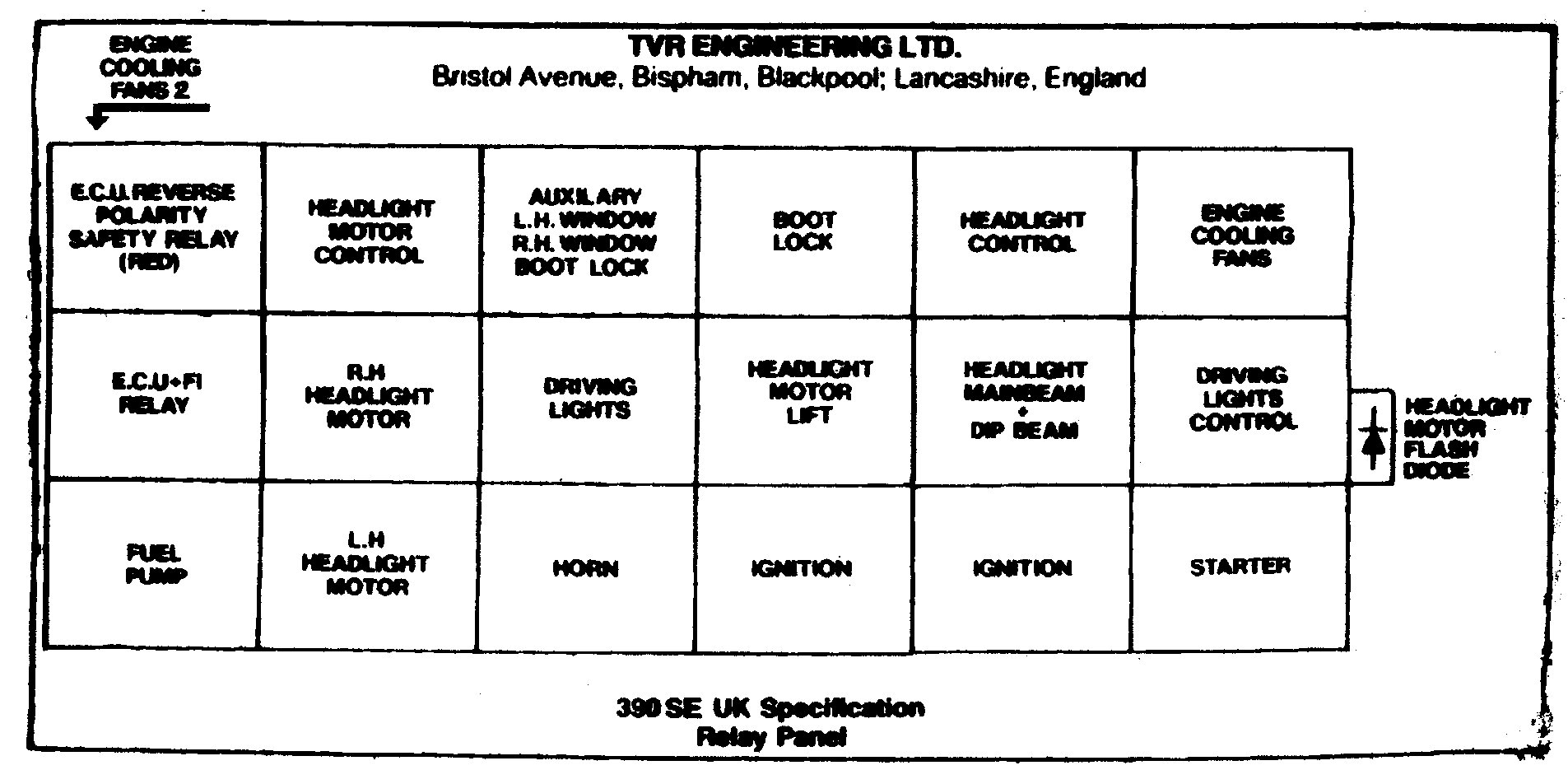
The relay labelled as the 'ECU reverse polarity safety relay (red)' is otherwise known as the 'steering module' or 'diode module'. They rarely go wrong, contain next to no components yet cost an absolute arm and a leg. Anyone with half an idea of electronics could build one from scratch for a fraction of the cost from LandRover dealers. The two relays labelled 'ignition' are wired in parallel and energise when the ignition key is turned on. They handle the loads of all ignition-switched items on the car, and despite being rated for 20 or even 30A each they can still suffer, either from arced contacts or overheating which causes them to melt and fall apart. Sometimes they take the relay socket with them! The labelling of the relays in the 'late headlamps' drawing above was taken from this diagram. The 'headlamp motor flash diode's can actually be two or even three diodes, often crimped to 1/4" Lucar connectors and pushed into the sockets. Although they rarely fail they can be inserted incorrectly in ways that can cause total chaos in the headlamp department... take careful note of their orientation.
Let there be (more) light...
I'd always been a shade irked by the feeble amount of light that the 390 seemed to throw at the scenery, which tended to make high-speed night-time thrashes on country lanes something of a tense experience. The Esprit had a superb set of 5.75" lamps that gave you FOUR main beams, and even on dip with just two units lit it was way better than the TVR. The time had come to do something about it. A quick rummage in the Vehicle Wiring Products catalogue turned up some new 7" lamp units for £32+ VAT... but I also thought that the tortuous route taken by the battery current to reach the lamps was perhaps contributing some voltage drop. Using the original colour-codes as a guide I ordered several metres of cable from VWP and, with two new relays, two new fuses and some new connectors, built a 'sub-harness' that takes power from the battery to the headlamps via the shortest practicable route. In the process I bypassed not only the entire fuse and relay system of the car but effectively deleted two connectors down in the nose as well. None of the car's wiring was touched or removed other than the short sections joining the headlamp bulbs to the main harness; I used the original 3-pin connector adjacent to the nearside light to provide control signals to my new sub-harness, the same connector on the offside being simply taped up. I even re-used the original headlamp fuses from the car's fusebox, replacing them with 5A ones as they don't need to handle any load now. As usual when I do most jobs I don't examine every angle before I start and sure enough my assumption that the old headlamp reflectors were tarnished proved to be wrong! It is a slim possibility that merely replacing the bulbs and cleaning the lenses would have made an improvement and saved some money, but what the hell :op
Fortunately the new installation DOES give an improvement - a bloody good one too! The dipped beam seems only marginally better but I suspect that's down to the lens design and resultant light pattern: modern cars seem to give a wider spread of light where these throw two nice bright pools... but only a few feet in front of the car! The main beam is much better though, and an odd spin-off is that the reduced load on the wiring inside the cabin has given the audio system a much-needed boost in the sense that it no longer cuts out due to voltage drop when the lights are on!