Lathes (Updated 20th November 2025)
Colchester Student Mk.2 (now sold, alas - but left here for information)
It wasn't as though my Boxford was exactly overworked or incapable of doing the odd jobs I use it for, but I found this Colchester for sale not far from my home so... I bought it! It was absolutely filthy, having apparently not been cleaned in several years. The swarf on the bed was inches deep and the splashback required cleaning with paraffin, a scraper and wire wool. It was missing the front electrical panel and the cover panel for the motor compartment (having been converted to single-phase by the previous owner), however the original main motor and suds pump were present, as were fixed and travelling steadies, faceplate and both 3- and 4-jaw chucks. The bed gap piece was installed and even the big spanner for the spindle locking ring was in its storage clips! The bed carried the 'induction hardened' label (and seemed to have minimal wear, though it may have been re-ground), the cross- and top-slide handles were the optional chrome items and the micrometer dials had both Imperial and Metric graduations which 'push-pull' under an alloy viewing window. The only really useful thing missing was the thread dial indicator (but see below!). Here's a 'before and after' comparison that shows you can often find nice machines hiding under layers of muck:
Dual-reading Metric/Imperial feedscrew dials:
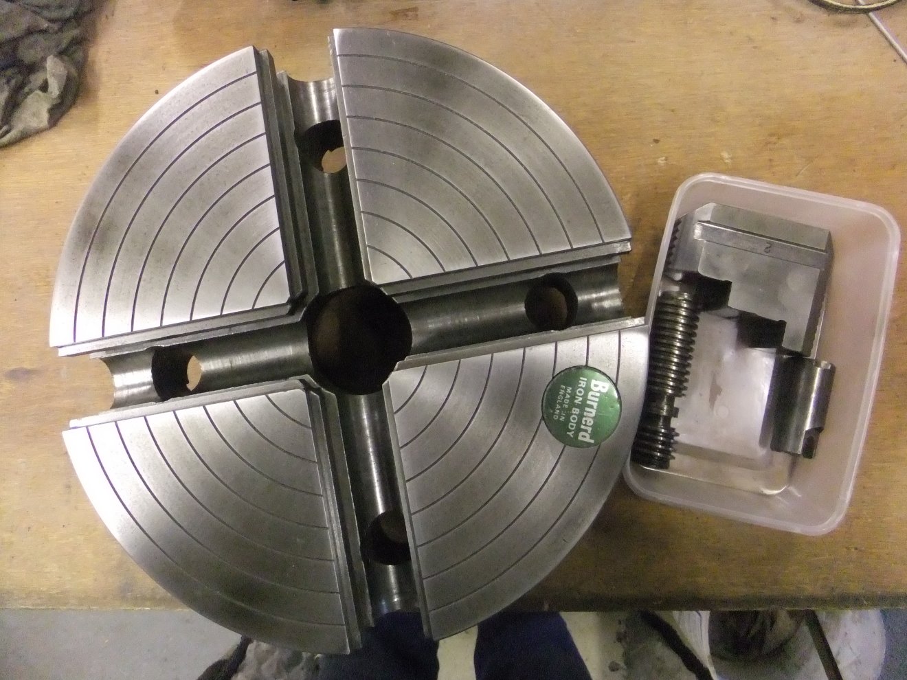
I don't think this 4-jaw has seen any serious action...
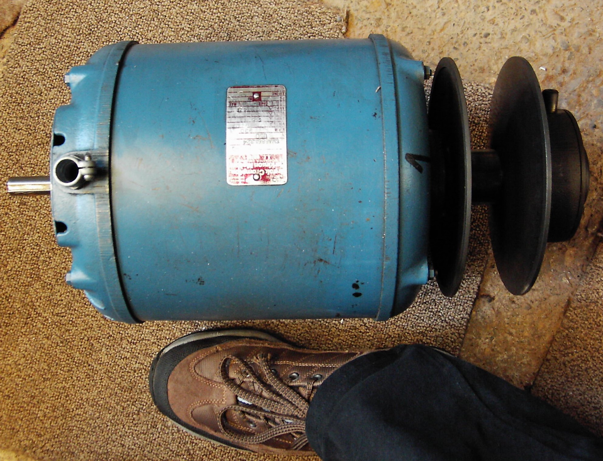
Right, so some months on when I'd finally got the Student positioned where I wanted it and in some condition as to be usable (oil in the headstock, always a good idea...) I did a few trial cuts and found a strange 'patterning' appearing on turned surfaces, irrespective of spindle speed, feeding manually or under power etc. At first I though the twin drive belts might be 'fighting' each other (one's a bit looser than the other) so I removed one and the marks were still there. I put a DTI on the chuck backplate, chucked a length of 1" steel bar and tried heaving the spindle around on its bearings but without proving any slack or wear that way. Finally I reinstalled the lathe's original 3-phase motor and bingo, mark-free finish. Phew. For a minute there I thought it was going to get expensive. All the original electrical control gear was missing from the Colchester so as a temporary measure I found a spare 3-phase DOL starter in a box of bits and screwed it to the wall next to the lathe. I fettled it eventually, as you'll see...
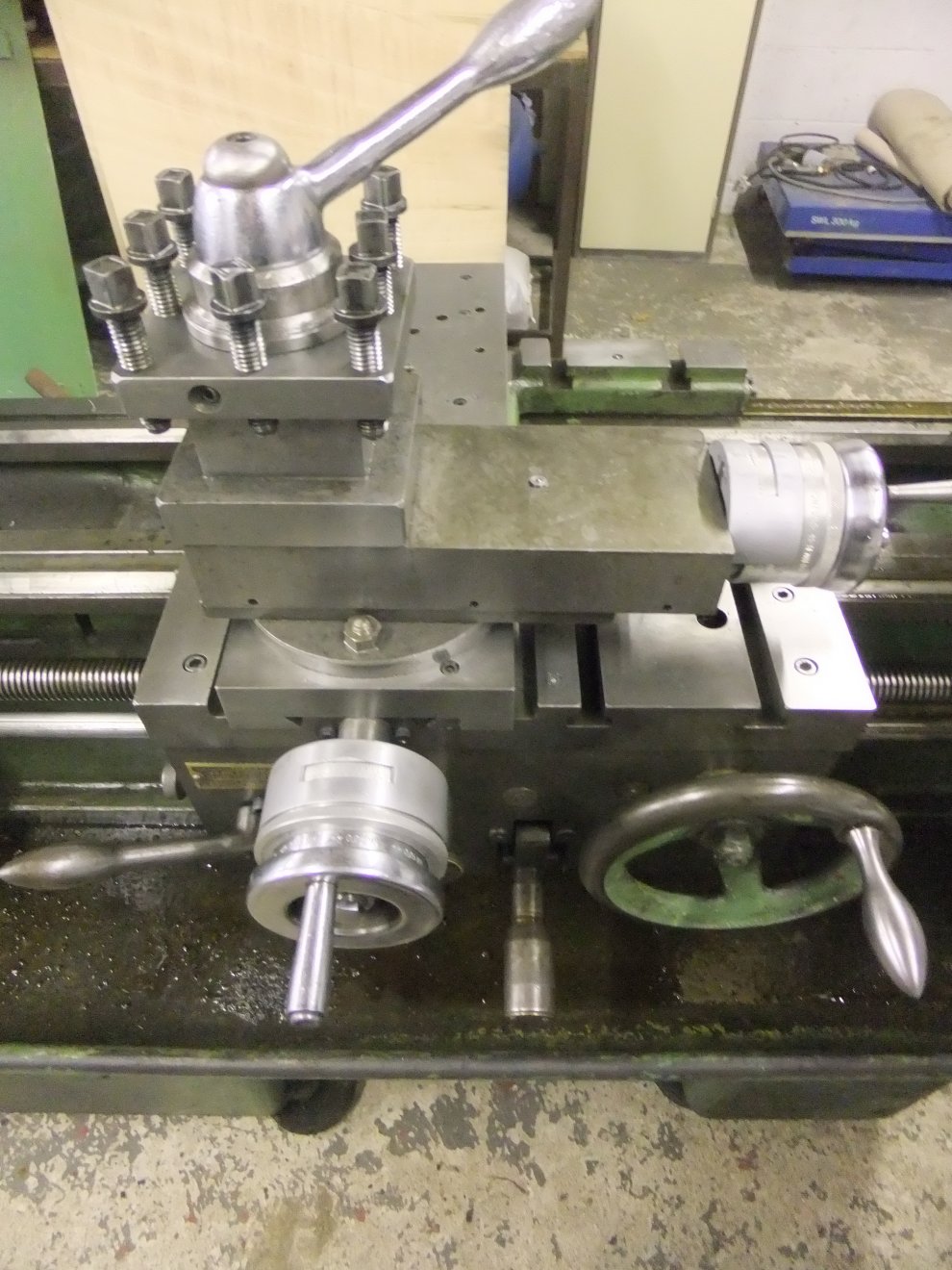
One delight of lathework that I had forgotten since I bought the AUD and VSL was the need to individually shim the cutting tool to correct height. The Colchester had its standard 4-way revolving toolpost which of course needs the tools shimming and that was one of the things that kept me from using it for so long - I could never seem to build a shim stack of the correct thickness.
I did encounter one somewhat serious issue: when taking a moderately heavy cut, the toolpost could be seen to be rocking! Close examination showed it to be the topslide moving on its base (the part with the rotation degree scale engraved on it) despite all the screws being tight. Oh, they were tight all right: someone had got so enthusiastic with the threadlock that I had to drill them all out. Turned out that surplus threadlock had been forced into the join between the slide and base, holding them apart. With this thin film shaved off and the mating faces polished up, the slide was refitted with new screws and just a modicum of threadlock... at which point the rocking disappeared. I don't know whether this cockup was down to the previous owner or the engineering company that claimed to have 'reconditioned' the lathe but clearly whoever had been using it must have been undiscerning about the quality of his work. By way of proof that I 'needed' a bigger lathe than the Boxford, I used the Colchester to skim car brake discs and drums that wouldn't fit onto the VSL. A mate with a Porsche 996 told me that they often fail MOTs when the rear discs corrode, but only on one side of each disc. Bizarre, but easily rectified on the Student.
That temporary DOL starter screwed to the wall was making the place look untidy, as were the gaping holes front and rear where the motor cover and electrical plate were absent. I'd tried emailing Colspares without success so I decided to make my own electrical panel and create some sort of vented sheet to close off the rear. A rummage in dark cupboards turned up a couple of ready-made louvred panels that I'd removed from an outdoor cabinet housing a customer's industrial oil cooler a few years back. The cooler was overheating so I'd replaced the louvres with a big cooling fan and decided the louvres were too useful to scrap! The louvred plate wasn't large enough to cover the lathe's opening but a bit of careful measuring showed that if I attached it to a sheet of alloy, the offcut from the centre of the alloy would be large enough to cover the opening in the front of the lathe and provide the basis for my electrical panel.


The louvred panel looks odd because it's on 'inside-out'; unfortunately I couldn't mount it the correct way around as the motor was in the way!
The original electrical components used by Colchester are long-since obsolete of course, but modern equivalents are available - and quite cheaply as well, thanks to a certain online auction site! I started off by designing a control circuit as I would if it was a for a job at work but it was getting over-complicated with transformers, 24V power supplies and so on so I elected to stick as closely as possible to the original design. This meant using contactors with 415V coils - and as it happens they sell for less than low-voltage items; largely I guess due to the move away from switching high voltages directly in machinery. Some control switches were needed as well but the usual Telemecanique items I work with are only rated for 240V. However Telemec's older switches were designed to work up to 600V and - oh look, some for sale cheaply on Ebay! A couple of snipe bids netted some motor overload units for the contactors and a cheeky 'best offer' got me a panel lamp with in-built 415V step-down transformer. A handful of DIN rail terminals and a 3-phase circuit breaker completed the ensemble which was duly mounted to the alloy plate and wired-up. Total expenditure less than thirty quid. Here's my control circuit (note it provides the necessary 'no-volt release' function for safety):-

...and it looks like this when assembled:


Update 270315:
I'd been on the lookout ever since I got the Student for a Thread Dial Indicator but either someone would outbid me or I thought the asking price was ludicrous - plus most of them seemed to be for the Mk1 Student rather than the Mk2. Based on the information on www.lathes.co.uk I figured that Colchester had probably not altered the fundamental design of the TDI between the models so I decided to take a punt on a TDI for a Mk1. A bold bid on Ebay netted one and, with bated breath I bolted it to the Student's carriage (the knurled nut was already there) and hit the start button. I needn't have worried: sure enough there's no operational difference and the TDI works fine. Its gear is in good shape so with the muck of decades cleaned off it was ready for action!

Yes, I know it's the wrong colour: you lot want the moon on a bloody stick sometimes! :D

Incidentally, if you wonder which marks to choose when threading and are puzzled as to why the lathe has no data plate to help you, the user manual does have the information hidden away in the chapter on thread-cutting... but blink and you'd miss it! Essentially, for even-numbered Imperial pitches (e.g. 12 tpi) you can engage the leadnut on any mark. For odd-number pitches (e.g. 13tpi) engage only on numbered marks and for fractional pitches (e.g. 7 and 3/4 tpi) engage only on number 1 mark. For Metric pitches you can't use the TDI but instead have to leave the leadnut engaged and run the lathe backwards to return to the start of the cut. To round off the story, due to those unexpected surprises life throws you I ended up selling the Student; it went to the Engineer in charge of the restoration of the Sir Nigel Gresley steam locomotive so it should continue to produce good work for a while yet.
Link to my home-brew 5C Collet Adapter for the Boxford VSL
My first machine tool was a 1920s lathe by Mellor, a long-gone company that was based in Huddersfield. That was replaced by a slightly more recent version of the same thing, then in 2004 I decided to take the plunge and bring my workshop kicking and screaming into at least the 1960s :) - so I bought a 1972 Boxford AUD. I'd had it less than a year when I found myself drooling over a Boxford VSL500 on - you guessed it - Ebay. The seller had a number of Boxfords that he'd bought from a school in Retford; one he'd kept for himself and the rest he was selling on to recoup the outlay of having to buy them as a job lot! In the event he did very nicely out of it; the first of two VSLs sold for £1800 which at the time was about top whack for an absolutely mint, hardly used example. These were good, but not THAT good. I knew I could sell my AUD for more or less what I'd paid - I'd put a reserve on to make sure - so I thought I'd chance my arm (by now suffering from lathe envy!) and put in a bid on the second VSL. To my surprise I 'won' the bidding (at a far more sensible price than that first VSL) and made the trip to Retford to collect my new toy. As it's an ex-school machine (the bed has a casting date of December 1977 so probably in service in 1978) it has of course done no real work, although several of the controls were seized, having evidently been neither used nor lubricated. The gearbox in particular was nigh-on impossible to operate until I'd spent a couple of hours squirting oil over the moving parts and working the levers. Fortunately the bedways, leadscrews etc. had been kept at least splash-lubed by the cutting oil and the spindle bearings are sealed-for-life so no issues there. The VSL is often regarded as the pinnacle of the Boxford non-CNC range. As well as having increased spindle bore it has the 'L00' fitting on the spindle nose which gives more positive location for chucks etc.; T-slots in the cross-slide to allow use as a milling table; and the pièce de resistance, continuously-variable speed control of the spindle. This was pre-inverter drive days of course, so they achieved it by having a system of expanding and contracting pulleys that are controlled by a dial on the front of the machine. Winding the dial clockwise effectively forces the pulleys to change diameter so the ratio between them changes and the spindle speeds up. The whole thing is propelled by an enormous 3-phase 415v motor. Changing that for a single-phase would, whilst not impossible, be an engineering challenge given the arrangement of the speed-change mechanism (as well as sacrilege!) so I opted to leave it in and fit an inverter (Variable-Frequency Drive). Now a lot of 'budget' VFDs take in 240v from a wall socket and output 3-phase... but at 240v. This means rewiring the motor windings to suit (not difficult) with an attendant reduction in the power of the motor. I turned to Ebay... and found a single-phase in, 3-phase at 415v out VFD. It wasn't cheap but by heck it's good. It was only the second time I'd ever worked with a VFD but I quickly realised that if I reinstalled the


Note the DRO for the Perrin at right; it's magnetic so can be positioned to suit the job. You can see the size of the VSL's motor in the following pic! The double-ended shaft allowed factory fitment of an electromagnetic spindle brake, not fitted to this machine as it was apparently an expensive option to have on a school lathe! Unfortunately it does make the VSL slightly longer than was my AUD and I had to rearrange a few things to make it fit the workshop.
I've found that used chucks etc. with the L00 fitting don't come along on Ebay very often. However a year after I bought the VSL, I happened upon the same Ebay seller listing a 3-jaw chuck. I got that for less than I thought it'd fetch (less than the seller hoped for too!)... the irony being that it may even be the original one for my lathe as he had several of them to start with and even admitted that some more tooling 'happened to turn up'. Hmmm. Anyway, a week or so later I found an ex-Harrison L00 faceplate for sale about 40 miles from me; I 'won' that auction and when I went to collect it the seller produced an L00 catchplate as well. It was a bit rusty so I haggled and got it for an additional few pounds. A couple of years previously I'd been given a brand-new 3-jaw 'Bison' chuck that had a plain-bore backplate fitted. Of course it wouldn't fit either my old Mellor or AUD so had languished in a cupboard, gathering rust (to my annoyance). I cleaned it up, machined a register on the 'new' catchplate to take it and to my surprise it works AND is accurate! Funny how these things work out, and proof that you should never throw anything away. The chuck-on-a-catchplate can be seen in the first photo of the lathe above. The VSL came fitted with a Dickson QCTP (Quick-Change Tool Post) but only very few toolholders so I've bought a couple more [EDIT 160225 - donkey's years later I finally got around to making some more, see here]. I'd seen a couple of website posts and YouTube videos where machinists have a DTI fitted to a Dickson holder and I thought that could be a useful addition. You can see how I got on on this page. I've even managed to acquire the 135/127 tooth conversion gear and the additional changewheels to allow this Metric VSL to cut Imperial threads.
A side-effect of the larger spindle is that the bore requires sleeving-down to suit various accessories, such as centres and collets. Boxford did offer a set of '5C'-sized collets with the attendant drawbar and spindle adapter, but these days you'd need a lottery win to afford one secondhand. Or is it just that people take the proverbial when they split the tooling from a lathe.. whatever, I'd like the facility to hold work in collets so the first step is to acquire, or more likely make, the necessary adapter. Actually no; the first step is to solve the mystery of the VSL's bore taper. Depending on which chapter of the internet you consult, you'll find that it's a MT4, MT5, even a MT4.5 and/or a Jarno #8...! As my VSL came with the standard-issue reducer to allow 3MT centres to be used, it struck me that all I needed to do was accurately measure the reducer, draw it in AutoCAD and let the program tell me the taper angle etc.
So I measured up and did the drawing and what it suggested was... none of the above. The nearest corresponding taper is MT3... but at a larger diameter. To prove it, I acquired a MT3 stub arbor. First off I fitted the factory adapter/reducer/sleeve/terminology of your choosing to the spindle and clocked the outer end of the bore with a DTI -to check that it was actually concentric with the spindle to start with! Then I plugged the arbor in and clocked the tiny amount of the taper that was accessible. OK so far. Next I clocked the parallel section of the arbor and found it was a few tenths out, so a light tickle with a tool got that to zero. Removing both adapter and arbor, I then fitted the 4-jaw chuck and installed the arbor, dialling it in to zero runout at the wide end of the taper (I'd marked the adapter and arbor in relation to the spindle key on the L00 taper as well). Now it was time to move the topslide round a tad and run it up and down the arbor taper, tapping the slide until there was as near zero displacement of the needle as I could get. Winding the topslide out, I slipped the spindle adapter onto the arbor and repeated the test. With exactly the same result. So there you have it: it's a 3MT but further 'up the slope', as it were. Here's the CAD I drew showing my adapter as measured vs. published data for the various tapers. Over the 2.375" span of the adapter, the same span (starting at the large end diameter as it's easier to measure) on any of the tapers other than the 3MT shows an obvious discrepancy at the small end. This, I suspect, explains why so many people say such-and-such a taper adapter 'almost fits'... the point being, the taper angle is the critical bit, not the diameter!

Next, of course, I need to find a suitable piece of bar stock so that I can start making the 5C collet adapter... well, how hard could it be? :D ...and to answer my own question, here's how I got on!